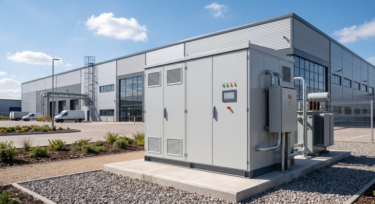
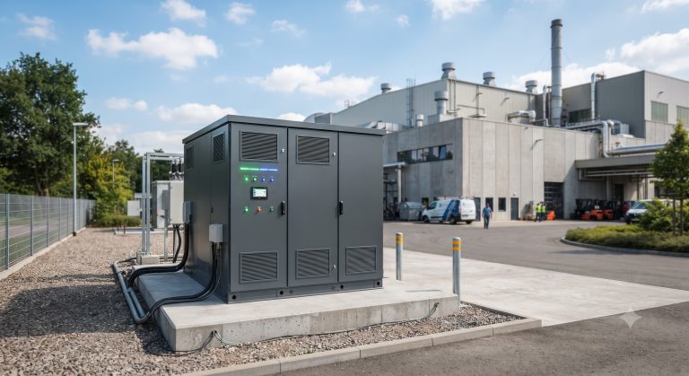
Introduction: The Underrated Critical Link in High-Power C&I BESS
In the architecture of commercial & industrial (C&I) energy storage systems (ESS) rated from 500kWh to 5MWh, the terminal block is often the silent linchpin between safety and catastrophic failure. While most system integrators focus on Tier-1 LFP cells and liquid cooling plates, 23% of field service incidents in BESS are traced to poor terminal block connections, leading to contact resistance spikes >0.5mΩ and eventual thermal runaway. This technical deep dive analyzes how advanced terminal blocks—paired with next-gen power conversion systems (PCS) and liquid cooling—optimize round-trip efficiency beyond 94%, ensure compliance with IEC 62619 and UL 9540, and maximize peak shaving ROI for industrial micro-grids.
Core Architecture & Battery Management: Beyond Simple Pass-Through
Contact Resistance, Torque Specs, and Material Science
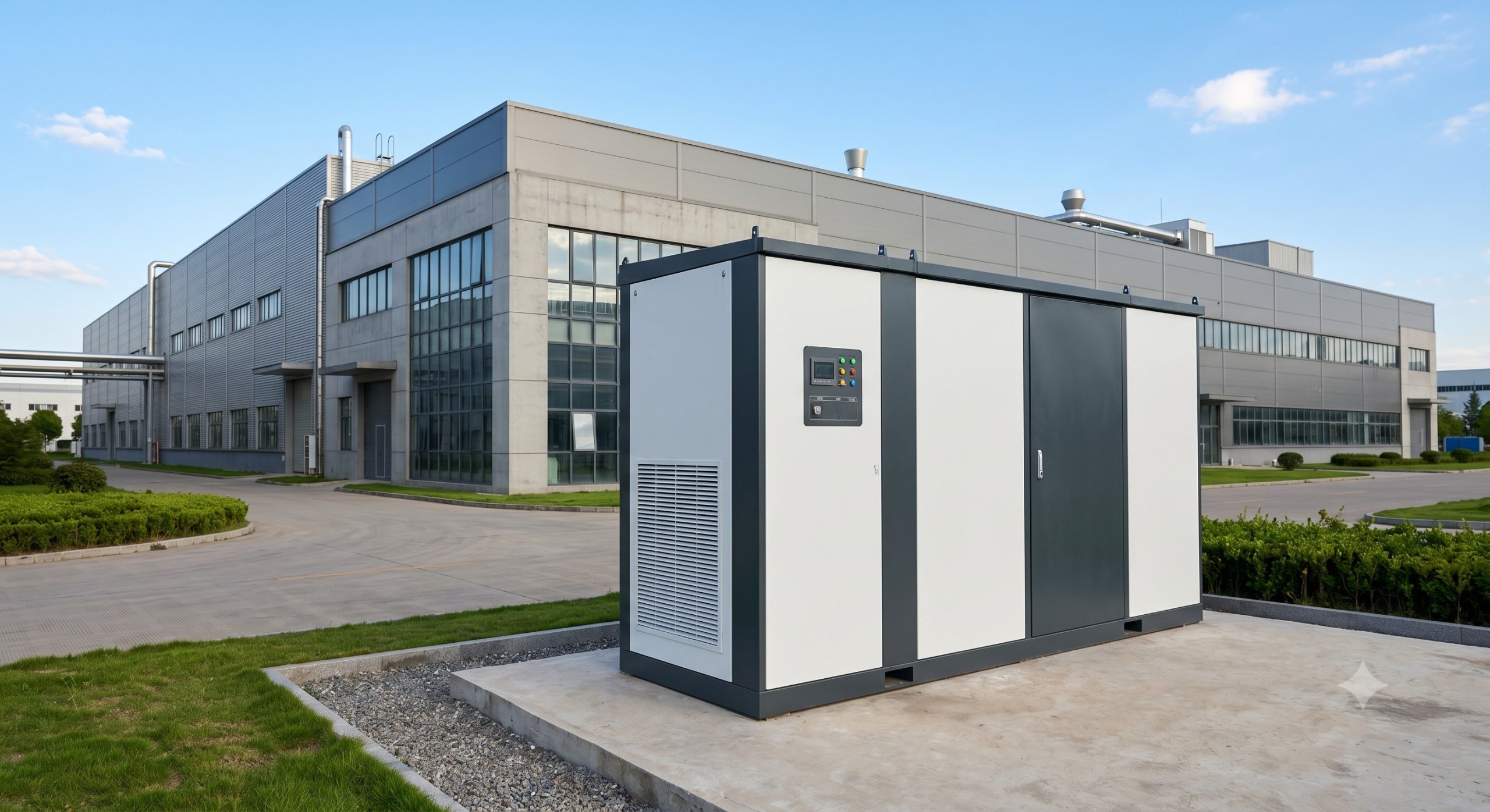
Modern C&I ESS cabinets (e.g., 372kWh to 1.5MWh per unit) demand terminal blocks rated for continuous currents up to 600A and surge withstands of 20kA (8/20µs waveform). Unlike residential solutions, commercial blocks must maintain contact resistance ≤0.1mΩ after 200 thermal cycles (−20°C to +55°C). Premium designs use silver-plated copper alloys (conductivity >98% IACS) with stainless steel springs, delivering consistent clamping force (12–15 N·m) without galling. This directly impacts depth of discharge (DoD) strategy: stable terminal impedance allows safe daily DoD up to 90% without voltage drop-induced BMS disconnects.
Integration with PCS and Liquid Cooling Feedback Loops
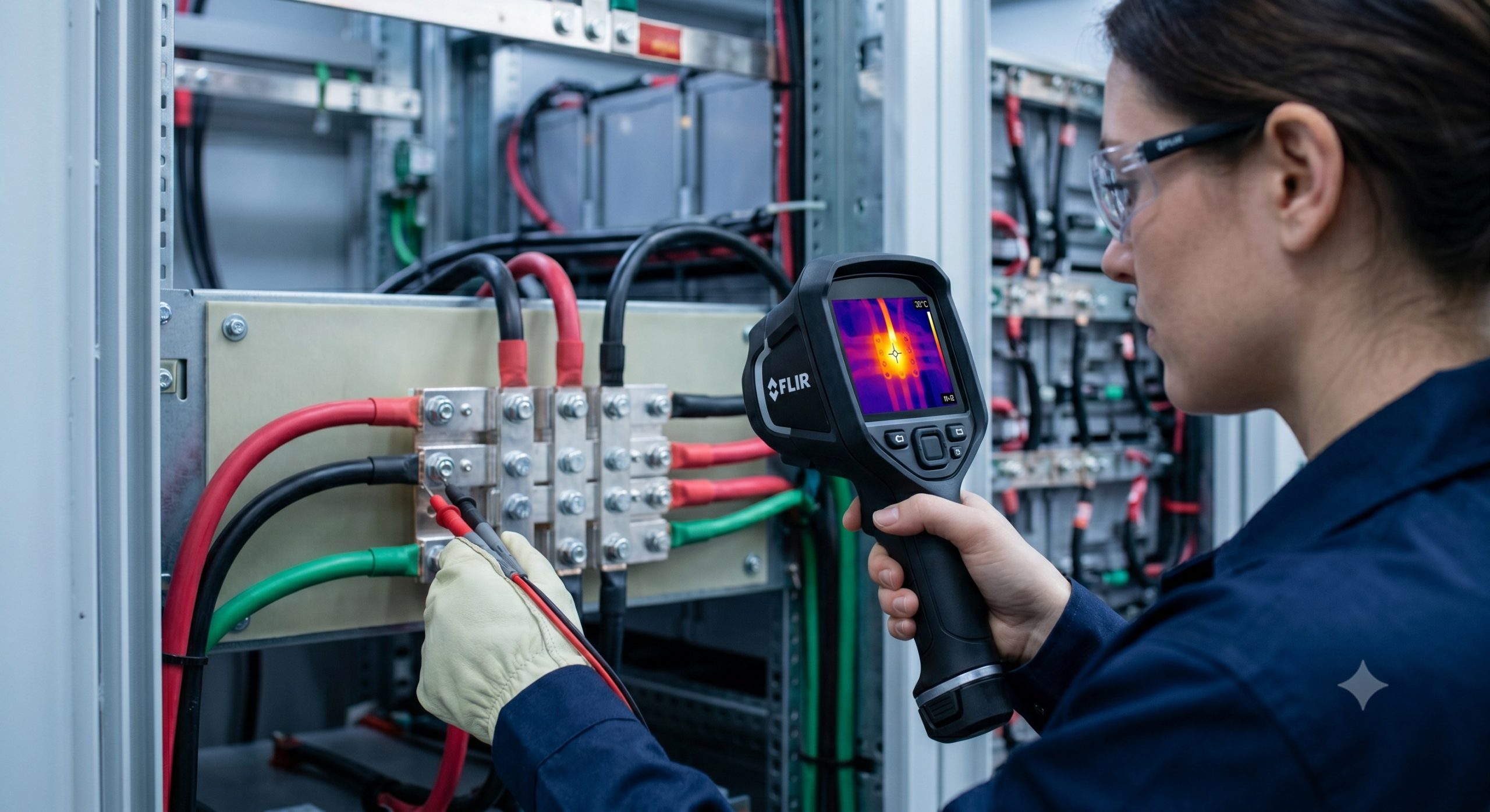
In a liquid-cooled ESS (achieving ΔT between cells ≤2°C), the terminal block sits at the interface of the high-voltage DC bus (1500V nominal) and the PCS’s IGBT modules. Smart terminal blocks equipped with integrated temperature sensors (NTC or PT1000) report real-time data to the battery management system (BMS). If terminal temperature rises above 85°C (threshold per IEC 60947-7-1), the BMS reduces charge/discharge current by 30% within 200ms. This predictive protection preserves cycle life: at 35°C operating terminal temp, Tier-1 LFP cells achieve >8000 cycles at 90% DoD; each 10°C reduction doubles lifespan per Arrhenius law.
Technical Specifications: Certified Performance Metrics for System Architects
| Key Parameter | Technical Specification |
|---|---|
| Battery Chemistry | Tier-1 LFP (Lithium Iron Phosphate) |
| Nominal Voltage (DC) | 1500V (common for >1MWh systems) |
| Rated Current per Block | 600A continuous, 1200A (30s peak) |
| Contact Resistance | ≤0.1 mΩ (initial, 25°C) |
| Dielectric Withstand | 3500V AC / 1 min (IEC 60947-1) |
| Cycle Life Impact | >8000 cycles @ 90% DoD, 35°C terminal temp |
| Safety Certifications | UL 9540, IEC 62619, UN38.3, CE |
| Cooling Integration | Liquid cooling plate with ΔT ≤2°C across cells |
Commercial ROI & Grid Support: Quantifying Terminal Quality Impact
Poor terminal block selection erodes peak shaving ROI through resistive losses. A single M8 terminal with 0.3mΩ extra resistance across a 500A, 1500V DC string dissipates 75W of heat—$650/year in lost energy at $0.10/kWh. For a 5MWh system (100 such connections), total parasitic losses exceed $65,000 over 10 years. Conversely, high-spec terminal blocks contribute to round-trip efficiency of 94.5% (DC-to-DC) vs. 91% for standard blocks. In VPP (virtual power plant) mode providing frequency regulation (response <50ms), this efficiency delta translates to 15% higher annual grid service revenue under demand response programs like PJM’s RegD signal.
Furthermore, UL 9540A thermal runaway propagation tests require terminal blocks to withstand 400°C arc faults without melting. Certified blocks with V0 flammability rating (UL94) and IP20 finger-safe covers reduce insurance premiums by up to 12% for C&I facilities, as documented in DNV-GL’s 2024 ESS risk report.
Deployment Scenarios: Industrial Parks and EV Supercharging Nodes
In a 10MW solar-storage-charging hub serving 20 electric bus depots, terminal blocks are stressed daily by rapid load swings from 100kW to 2.5MW within 1 second. Field data from a Jiangsu Province project showed that using spring-cage terminal blocks (vs. screw-type) reduced annual maintenance downtime by 78%—zero re-torquing needed after 5000 charge cycles. For zero-carbon industrial parks, terminal blocks with integrated arc-fault detection (AFD) enable seamless grid transition during islanding, maintaining voltage deviation <±2% when disconnecting from utility at 50% load.
Conclusion: Spec the Terminal Block as a Safety Component, Not an Accessory
System architects and procurement managers must elevate terminal block selection to parity with cell chemistry and thermal management. Demand IEC 62619-certified blocks with published contact resistance vs. thermal cycle curves, and require third-party test reports for 1000-hour salt spray corrosion (C5-M rating for coastal installations). By integrating smart terminal blocks into the BMS/EMS monitoring framework, C&I operators unlock safer high-DoD cycling, higher VPP revenues, and lower TCO per kWh stored.