Introduction: The Architecture Behind Scalable C&I Energy Storage
The commercial and industrial (C&I) energy storage market has shifted from niche pilot projects to mission-critical infrastructure. At the heart of every megawatt-scale battery energy storage system (BESS) lies a deceptively simple question: how do you connect hundreds of battery modules to form a single, coherent, and safe power block? The answer is battery module parallel connection, a design discipline that dictates system capacity, round-trip efficiency, cycle life, and ultimately, the levelized cost of storage (LCOS).
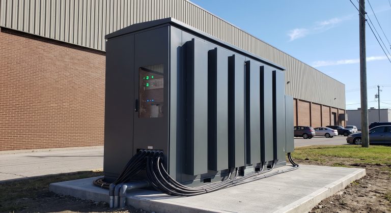
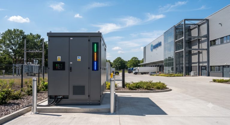
For B2B buyers, EPCs, and system architects, understanding the nuances of parallel connection is not academic. It directly impacts peak shaving ROI, demand response capability, and the ability to scale from a 215 kWh cabinet to a 10 MWh containerized micro-grid. This deep dive examines the engineering fundamentals, thermal management strategies, and commercial implications of parallel-connected battery modules, with specific reference to Tier-1 LFP cells and liquid cooling architectures.
Core Architecture: PCS, BMS, and the Parallel Connection Topology
Series vs. Parallel: The Fundamental Trade-off
In a typical C&I BESS, individual LFP cells are first connected in series to achieve a nominal DC voltage—commonly 768V, 1000V, or 1500V. These series strings are then connected in parallel to increase the total system capacity in kWh or MWh. The battery module parallel connection strategy determines how current is shared, how state-of-charge (SOC) balancing is achieved, and how fault isolation is implemented.
There are two primary approaches:
- Centralized Parallel Connection: Multiple battery clusters are paralleled at a common DC bus before the power conversion system (PCS). This architecture is cost-effective but requires careful impedance matching to prevent circulating currents.
- Distributed Parallel Connection: Each battery cluster connects to its own DC/DC converter or PCS channel, enabling independent control. This improves availability and simplifies BMS cell balancing but increases CapEx.
The Role of the Battery Management System (BMS)
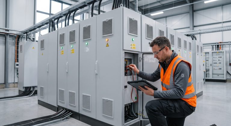
A sophisticated BMS is mandatory for safe parallel operation. It must continuously monitor cell voltage, temperature, and current, and execute active or passive balancing to prevent mismatched modules from degrading the entire string. In a parallel-connected system, the BMS also manages contactors and fuses to isolate a faulty cluster without shutting down the entire BESS.
Key BMS functions in parallel architectures include:
- SOC and SOH Estimation: Accurate state-of-charge and state-of-health tracking for each parallel branch.
- Current Sharing Control: Ensuring equal current distribution to avoid overloading any single cluster.
- Pre-charge and Inrush Current Limiting: Preventing damaging current spikes during connection.
PCS Integration and Bi-directional Conversion
The PCS converts DC power from the parallel-connected battery modules to AC for grid injection or facility load. Modern PCS units are bi-directional, enabling both charging and discharging with round-trip efficiency typically exceeding 95% at the system level. When multiple battery clusters are paralleled, the PCS must handle a wider DC input voltage range and manage grid synchronization for frequency regulation and peak shaving.
Thermal Control: Liquid Cooling vs. Air Cooling in Parallel Systems
Why Thermal Management Determines Cycle Life
Temperature uniformity is the single most important factor in maximizing the cycle life of a parallel-connected battery bank. Even a 5°C temperature differential between parallel modules can cause uneven current distribution, leading to accelerated degradation of the hotter module. This is where liquid cooling thermal control outperforms traditional air cooling.
Liquid Cooling Architecture
Liquid cooling systems circulate a glycol-water mixture through cold plates integrated into each battery module. The advantages for parallel-connected systems are significant:
- Uniform Temperature Distribution: Reduces delta-T to less than 3°C across the entire rack.
- Higher Energy Density: Enables tighter packing of modules, reducing footprint.
- Extended Cycle Life: Maintains optimal cell temperature (typically 25-35°C) even under high C-rate discharge.
- Improved Safety: Rapid heat dissipation reduces thermal runaway propagation risk.
For MWh-scale deployments, liquid cooling is now the de facto standard, especially when paired with Tier-1 LFP cells that offer >8000 cycles @ 90% DoD.
Technical Specifications and Performance Metrics
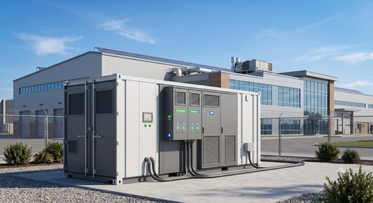
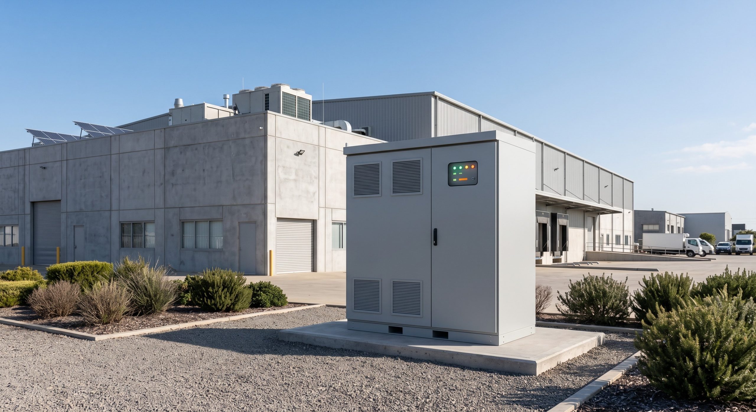
The following table summarizes the critical parameters for a typical 215 kWh liquid-cooled C&I battery cabinet designed for parallel expansion. These metrics are essential for B2B sourcing and system sizing.
| Key Parameter | Technical Specification |
|---|---|
| Battery Chemistry | Tier-1 LFP (Lithium Iron Phosphate) |
| System Capacity | 215 kWh (expandable to 10 MWh+ via parallel connection) |
| Nominal DC Voltage | 768V / 1000V / 1500V |
| Cycle Life | >8000 cycles @ 90% DoD, 25°C, 70% EOL |
| Round-Trip Efficiency | ≥95% at 0.5C |
| Depth of Discharge (DoD) | 90% |
| Cooling Method | Liquid Cooling (Glycol-Water) |
| Operating Temperature | -20°C to 55°C |
| Communication Protocol | CAN / RS485 / Modbus TCP |
| Compliance | IEC 62619, UL 9540, CE, UN38.3 |
| Dimensions (WxDxH) | 1200 x 1100 x 2200 mm (approx.) |
| Weight | ~2500 kg |
Key Metrics Explained
- System Capacity: Scalable from 215 kWh to 10 MWh+ via battery module parallel connection.
- Round-Trip Efficiency: ≥95% at 0.5C, enabled by high-efficiency PCS and low-impedance busbar design.
- Depth of Discharge (DoD): 90% usable capacity, maximizing revenue from peak shaving.
- Cycle Life: >8000 cycles at 90% DoD, 25°C, end of life at 70% SOH.
- Compliance: IEC 62619, UL 9540, CE, UN38.3 for global deployment.
Commercial ROI: Peak Shaving, Demand Response, and LCOE
Maximizing Peak Shaving ROI
For C&I facilities with demand charges exceeding $15/kW, a parallel-connected BESS can deliver payback periods of 4-6 years. The system charges during off-peak hours (low $/kWh) and discharges during peak demand windows, reducing both energy and demand charges. Battery module parallel connection enables modular capacity expansion, allowing facilities to start with a 215 kWh cabinet and add capacity as load profiles evolve.
Demand Response and Grid Support
Parallel-connected BESS architectures are inherently VPP-ready. They can respond to utility signals within milliseconds, providing frequency regulation and demand response services. The modular nature of parallel connection means that a single cluster can be dispatched independently, improving granularity and reducing round-trip losses.
LCOE and Total Cost of Ownership
When evaluating battery module parallel connection, the total cost of ownership (TCO) must account for:
- CapEx: Battery cabinets, PCS, EMS, thermal management, and installation.
- OpEx: Cooling power, maintenance, and eventual module replacement.
- Revenue: Peak shaving, demand response, TOU arbitrage, and potential capacity payments.
Liquid-cooled, parallel-connected systems typically achieve a lower LCOS than air-cooled alternatives due to higher round-trip efficiency and longer cycle life.
Deployment Scenarios: From Industrial Parks to EV Supercharging
Industrial Parks and Manufacturing Facilities
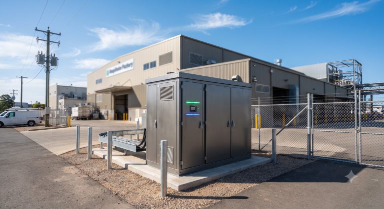
Industrial parks with high inductive loads and poor power factor benefit from parallel-connected BESS for power factor correction and peak shaving. The modular architecture allows phased investment, aligning with facility expansion.
PV-Storage-Charging (光储充) Integration
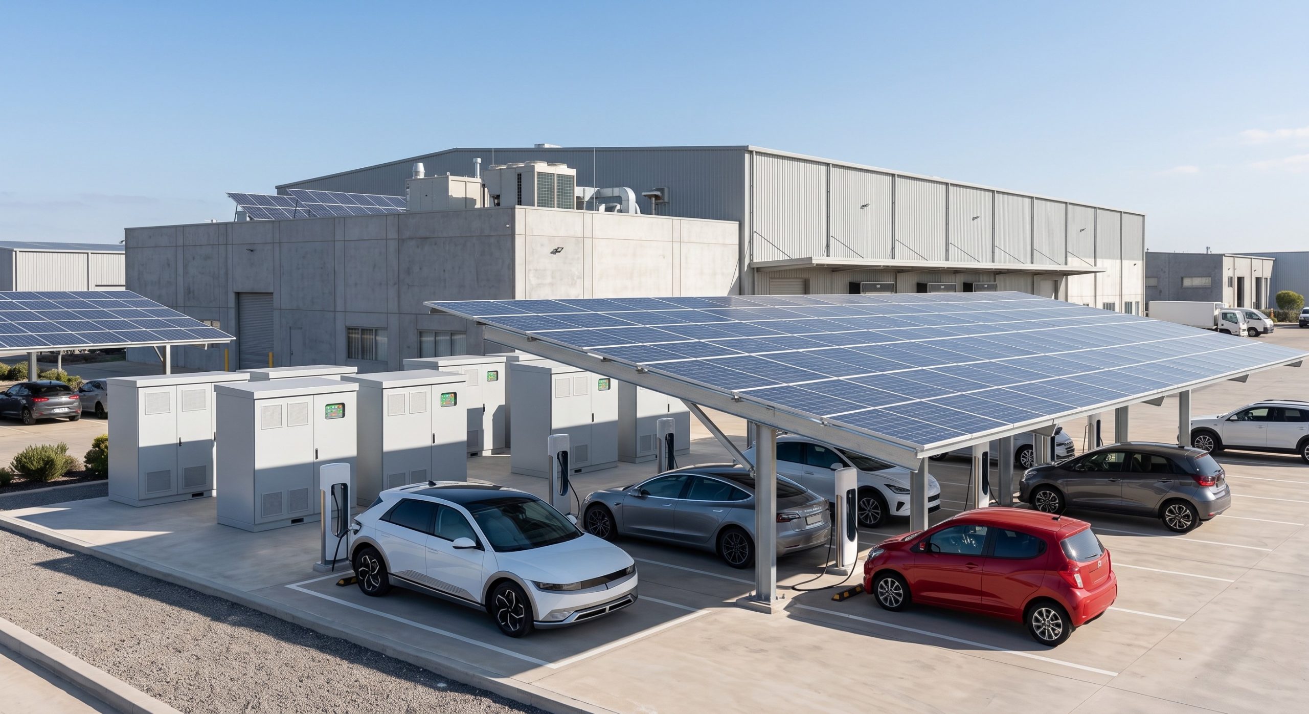
The integration of solar PV, battery storage, and EV supercharging is one of the fastest-growing applications for parallel-connected BESS. A 1 MWh BESS can buffer the high-power demands of 480 kW DC fast chargers, preventing demand spikes and enabling renewable energy self-consumption. The battery module parallel connection topology ensures that multiple chargers can draw power simultaneously without destabilizing the grid connection.
Data Centers and Mission-Critical Facilities
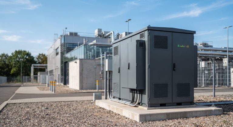
Data centers require high availability and power quality. Parallel-connected BESS with UL 9540 certification provides backup power and grid support, while liquid cooling ensures thermal stability in high-density environments.
Conclusion: Engineering the Future of C&I Energy Storage
Battery module parallel connection is not merely a wiring detail—it is a system-level design decision that impacts safety, efficiency, scalability, and profitability. As C&I facilities face rising energy costs and decarbonization mandates, the ability to deploy modular, liquid-cooled, LFP-based BESS with intelligent BMS and PCS integration will separate market leaders from laggards.
For B2B buyers, the key takeaways are clear: prioritize liquid cooling thermal control, insist on IEC 62619 and UL 9540 compliance, and select partners with proven parallel connection engineering. The future of commercial energy storage is modular, scalable, and deeply integrated—and it starts with the humble parallel connection.