TURNKEY HARDWARE INTEGRATION & SAFETY SPECIFICATION
EQUIPMENT INTRODUCTION
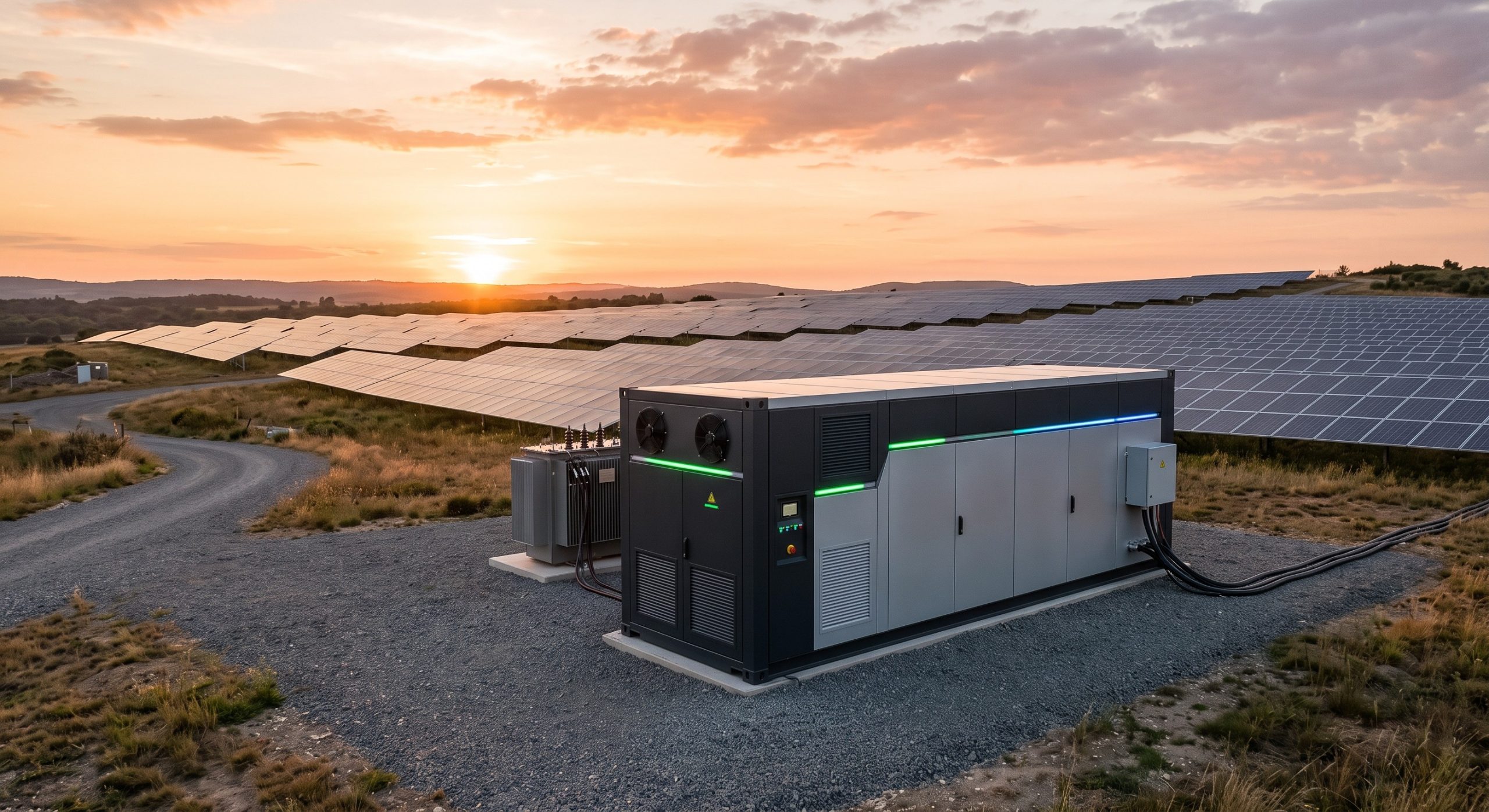
The Hybrid Inverter and Battery Pairing Manual serves as the definitive engineering reference for the integration of bi-directional power conversion systems with high-voltage lithium iron phosphate (LFP) battery cabinets. This document establishes the mandatory hardware pairing protocols, communication handshakes, and safety interlocks required to deploy a Tier-1 commercial and industrial energy storage system. The platform is engineered for seamless interoperability, ensuring that the hybrid inverter and battery enclosure operate as a unified, grid-forming asset capable of peak shaving, demand response, and backup power delivery.
This manual is intended for certified system integrators, EPC contractors, and facility engineers responsible for the physical assembly, electrical termination, and commissioning of the storage plant. Adherence to the pairing specifications herein is a prerequisite for warranty validation and regulatory compliance under UL 9540 and IEC 62619.
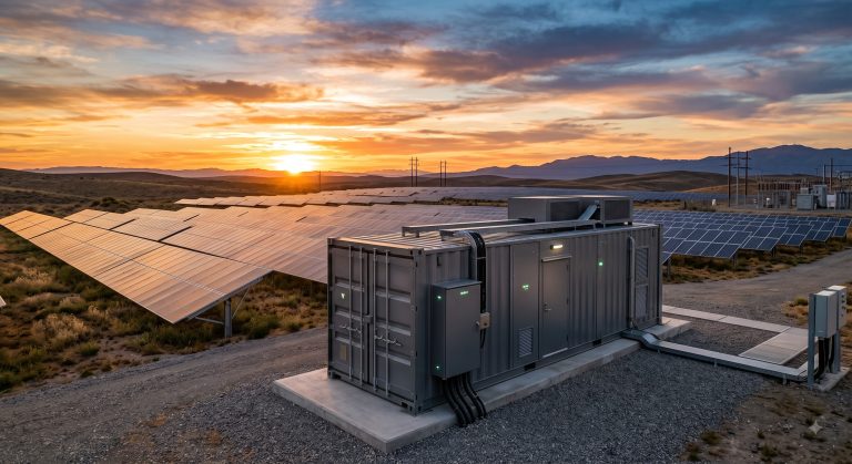
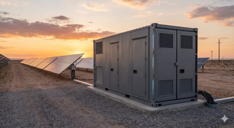
OUTDOOR PAD PREREQUISITES
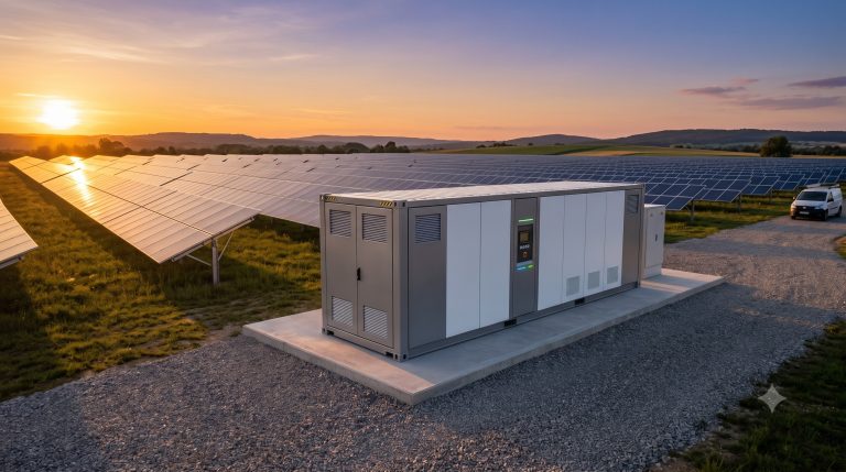
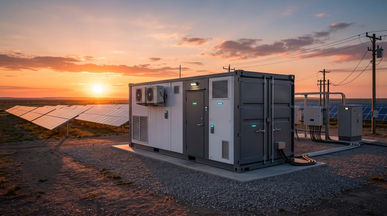
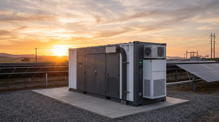
Prior to mechanical and electrical coupling of the hybrid inverter and battery cabinet, the installation site must satisfy the following civil and environmental prerequisites.
Foundation Requirements: The concrete pad must be level within a tolerance of 3 mm per meter, capable of sustaining a static load of no less than 1,200 kg/m2. A minimum clearance of 1,000 mm around the cabinet perimeter is required for thermal exhaust and service access.
Cable Routing: Trenches or cable trays must be sized to accommodate the DC busbar interconnect, AC grid interface cables, communication harnesses (CAN 2.0B / RS-485), and the liquid cooling loop supply and return lines. All conduits must be sealed against rodent ingress and moisture accumulation.
Grounding: A dedicated earth ground electrode with a resistance of less than 4 ohms must be established. The hybrid inverter chassis, battery cabinet frame, and DC negative bus must be bonded to this common reference point prior to energization.
Environmental Enclosure: The outdoor pad must be rated for the local seismic zone. If the installation is in a coastal or high-humidity environment, supplemental corrosion protection for the cable glands and busbar joints is mandatory.
BMS BALANCING PROTOCOLS
The Battery Management System (BMS) is the central intelligence responsible for cell-level safety, state-of-charge (SOC) calibration, and active equalization. The following pairing logic must be observed during commissioning.
Pre-Charge Handshake: The hybrid inverter must initiate a low-voltage pre-charge sequence to the battery cabinet before closing the main DC contactors. This prevents inrush current from damaging the DC link capacitors and the BMS shunt. The pre-charge resistor circuit must be verified for continuity prior to first power-up.
CAN Bus Address Assignment: Each battery cabinet in a parallel string must have a unique CAN bus address. The master BMS communicates with the hybrid inverter via a designated protocol (e.g., Modbus TCP or CANopen). The inverter firmware must be configured to recognize the exact number of battery cabinets connected. A mismatch between the physical cabinet count and the inverter’s configured count will result in a permanent lockout.
Active Equalization Threshold: The BMS performs continuous cell voltage monitoring. When the delta between the highest and lowest cell voltage exceeds 50 mV, the active balancing circuit activates. The hybrid inverter must be set to a constant-voltage (CV) charging mode during this period to prevent overvoltage on the highest cell. The equalization current is limited to 2 A per cell string.
State-of-Charge (SOC) Calibration: Upon first commissioning, a full charge-discharge cycle must be executed to calibrate the SOC coulomb counter. The hybrid inverter must be programmed to charge the battery to 100% SOC (3.65 V per cell) and discharge to 5% SOC (2.8 V per cell) at a rate not exceeding 0.5C. This ensures the accuracy of the depth-of-discharge (DOD) calculations used by the energy management system (EMS).
KEY FEATURES
– Bi-Directional Power Conversion: The hybrid inverter supports seamless transition between grid-tied, islanded, and backup modes with a transfer time of less than 20 ms.
– High-Voltage DC Coupling: The system operates on a 1,000 V DC bus, reducing cable cross-sections and resistive losses between the battery cabinet and the inverter.
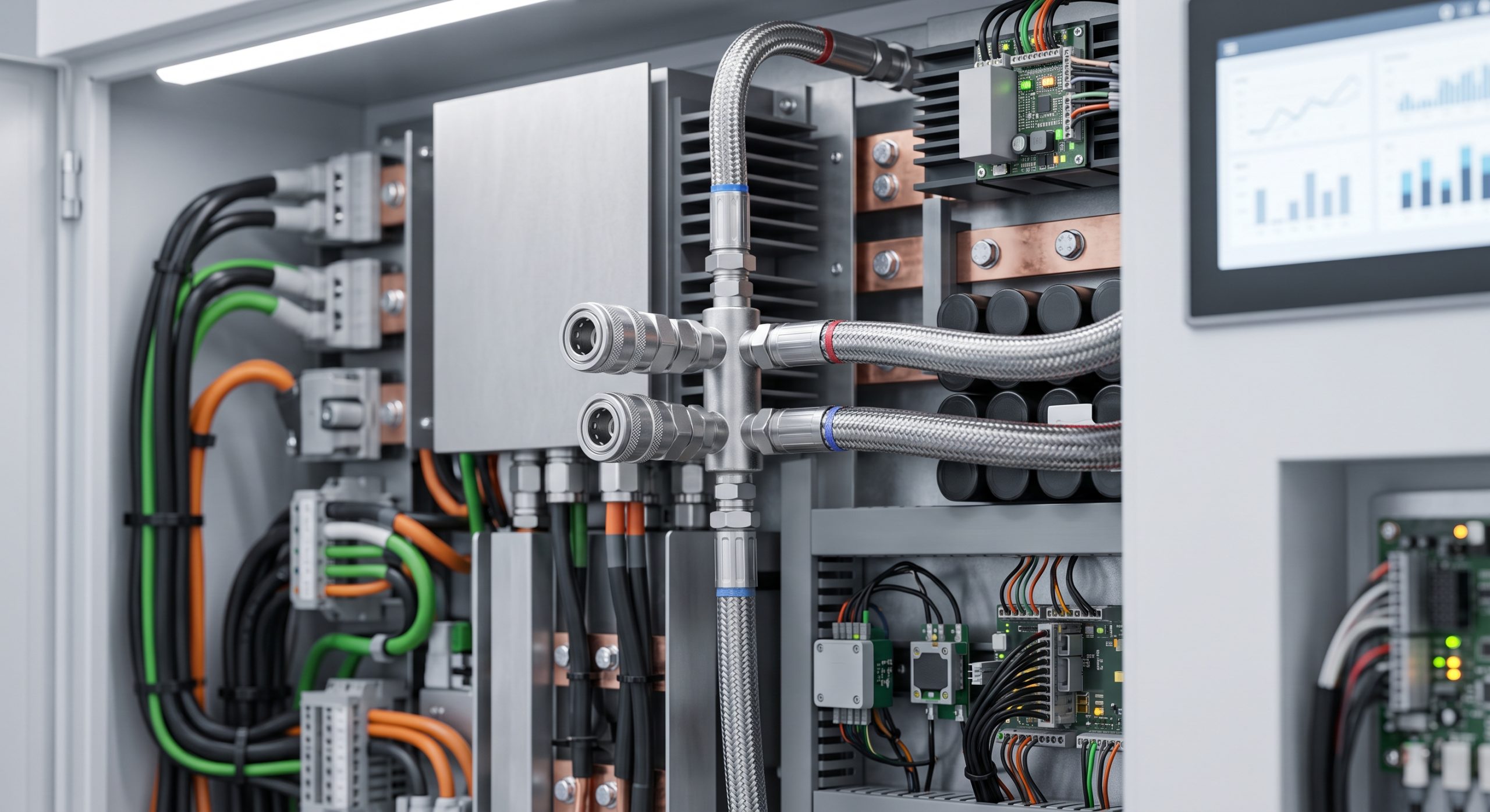
– Integrated Liquid Cooling Interface: Quick-connect fluid couplings allow for rapid pairing of the battery cabinet’s thermal management loop with the inverter’s cold plate circuit.
– Multi-Level Safety Interlocks: Hardware and software interlocks prevent contactor closure under fault conditions, including over-temperature, over-voltage, and ground fault detection.
– Modular Parallel Expansion: Up to 8 battery cabinets can be paralleled per hybrid inverter, with automatic load sharing and SOC balancing.
VERIFIED SPECS
| Parameter | Specification |
|---|---|
| Nominal Capacity | 215 kWh / 372 kWh per cabinet |
| Cooling Method | Smart Liquid Cooling |
| Cell Chemistry | Tier-1 LFP |
| DC Bus Voltage | 1,000 V DC |
| AC Grid Interface | 400 V AC, 3-Phase, 50/60 Hz |
| Max. Round-Trip Efficiency | 95% |
| Depth of Discharge (DOD) | 95% |
| Communication Protocol | CAN 2.0B / Modbus TCP |
| Ingress Protection | IP54 (Outdoor) |
| Operating Temperature | -20 to +55 degrees Celsius |
| Certifications | UL 9540, IEC 62619, CE |
| Warranty | 10 Years / 6,000 Cycles |
LOCAL O&M MAINTENANCE LOGIC
The pairing of the hybrid inverter and battery cabinet requires a structured operations and maintenance (O&M) regime to ensure a 15-year design life.
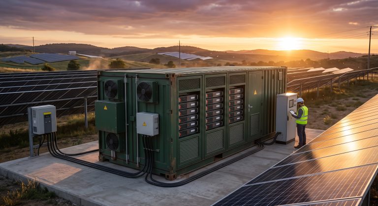
Quarterly Inspection: Verify the torque of all DC busbar connections to 25 Nm. Inspect the liquid cooling loop for leaks, pressure drop, and coolant pH. Check the BMS firmware version against the inverter’s compatibility matrix.
Annual Capacity Test: Perform a controlled discharge from 100% to 10% SOC at 0.5C to measure round-trip efficiency and capacity retention. If capacity falls below 80% of nominal, initiate a warranty claim.
Coolant Replacement: Replace the glycol-water mixture every 5 years or if the freeze point rises above -20 degrees Celsius. Flush the loop with deionized water before refilling.
Firmware Management: Only apply firmware updates that are jointly validated by the inverter and battery OEM. Asymmetric firmware versions can lead to communication timeouts and forced shutdowns.
📥 Download Technical Specification
Click the button below to view or download the full official PDF datasheet.