EXECUTIVE SUMMARY
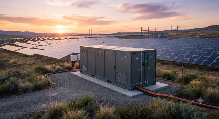
This document provides authoritative, OEM-grade guidance for the parallel wiring of battery clusters in commercial and industrial (C&I) battery energy storage systems (BESS). As global demand accelerates for scalable, high-reliability storage platforms, the correct implementation of parallel cluster architectures is critical to maximizing system availability, safety, and lifetime performance. This technical overview delineates the electrical topology, busbar interfaces, balancing protocols, and safety mechanisms required for robust parallel expansion of Tier-1 LFP battery clusters. It is intended for system integrators, EPC contractors, and asset owners deploying MWh-scale storage assets.
SYSTEM ARCHITECTURE & SAFETY
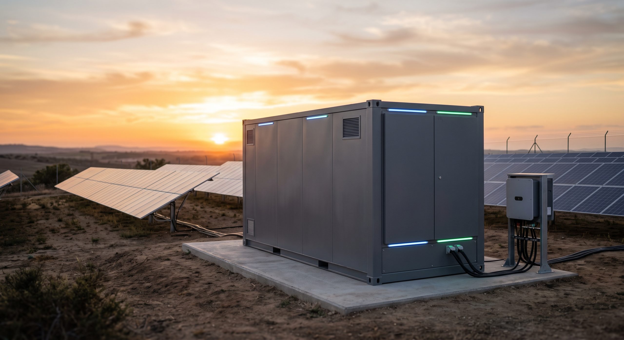
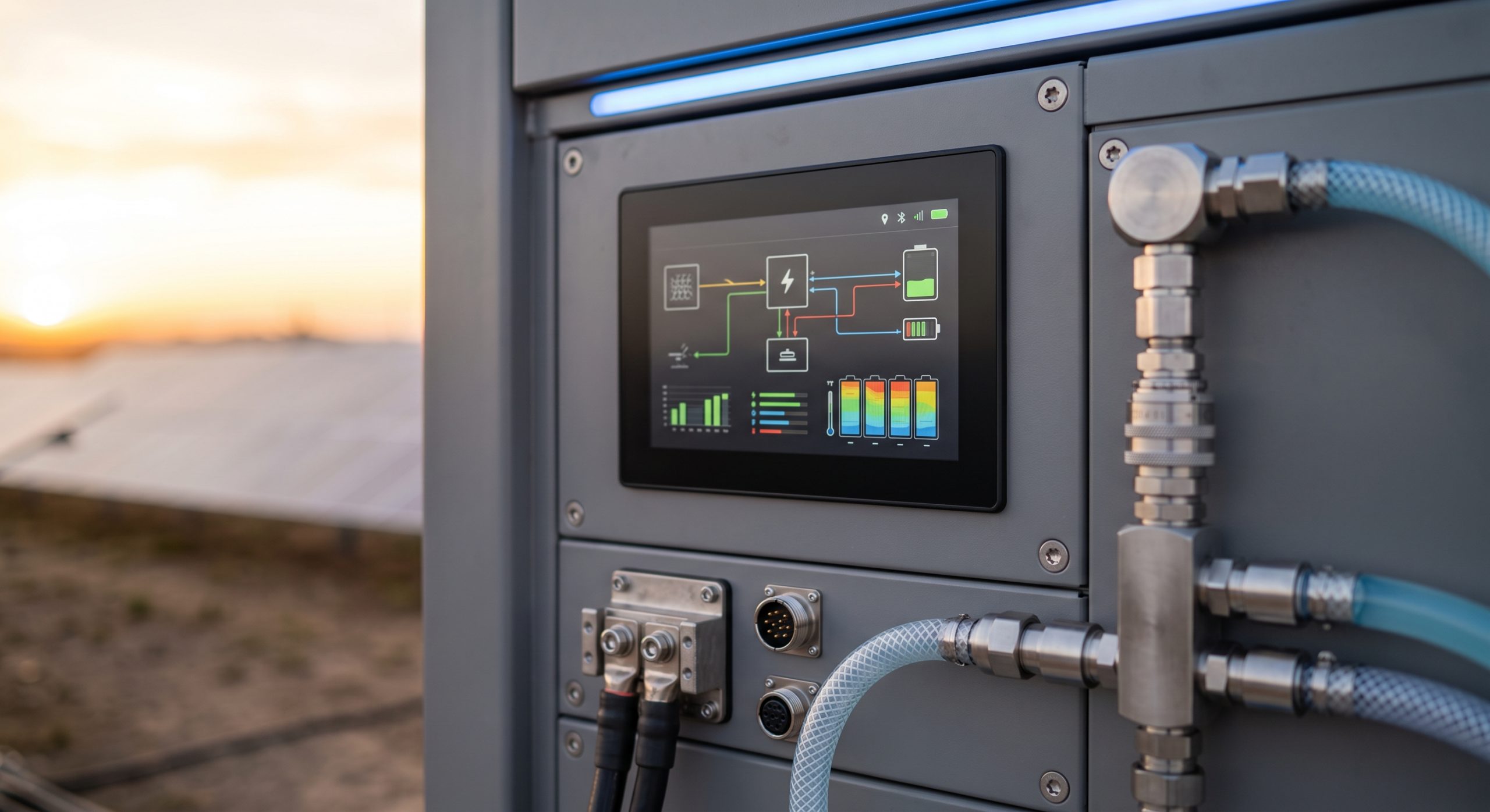
The parallel wiring of battery clusters is engineered around a common DC bus architecture that aggregates multiple battery cabinets or racks. Each cluster comprises series-connected LFP modules managed by a dedicated Battery Management System (BMS), which communicates with the central Energy Management System (EMS) via CAN or Ethernet. Parallel connections are established at the DC busbar level, with each cluster protected by individual DC circuit breakers and fuses rated for the system’s maximum fault current. Critical safety considerations include: (1) ensuring identical cluster voltage and state-of-charge (SOC) prior to paralleling to prevent circulating currents; (2) utilizing pre-charge circuits to limit inrush current during connection; (3) implementing reverse-polarity and short-circuit protection; and (4) adhering to clearance and creepage distances per IEC 62619 and UL 9540A. The architecture supports hot-swap maintenance and N+1 redundancy, enabling seamless capacity expansion without system downtime.
KEY FEATURES
– Scalable Parallel Expansion: Supports up to 8 clusters in parallel per PCS, enabling flexible capacity from 215 kWh to 3.44 MWh per bus.
– Active Cluster Balancing: BMS-coordinated SOC equalization reduces circulating currents to <2% of nominal current.
- Pre-charge & Soft-Start: Integrated pre-charge circuit limits inrush to <10% of peak fault current, protecting contactors and busbars.
- Smart Busbar Monitoring: Real-time temperature and current sensing at each parallel tap point, with alarm thresholds at 80°C.
- Fault Isolation: Individual cluster DC breakers enable rapid disconnection of a faulty string without affecting parallel operation.
- Compliance-Ready: Designed to meet UL 9540, IEC 62619, and NFPA 855 for parallel-connected ESS.
COMPLIANCE & STANDARDS
All parallel wiring instructions and hardware configurations are validated against the following international standards: UL 9540 (Energy Storage Systems and Equipment), UL 9540A (Thermal Runaway Fire Propagation), IEC 62619 (Secondary Cells and Batteries for Industrial Applications), IEC 62933-5-2 (Grid-Integrated ESS Safety), NFPA 855 (Installation of Stationary ESS), and IEEE 1547 (Interconnection of Distributed Energy Resources). The busbar and cabling sizing follow NEC Article 706 and IEC 60364-7-712. Documentation includes arc-flash hazard analysis and short-circuit current calculations for each parallel configuration.
TECHNICAL SPECIFICATIONS
[Text...]
| Parameter | Specification |
|---|---|
| Nominal Capacity | 215 kWh / 372 kWh per cabinet |
| Cooling Method | Smart Liquid Cooling |
| Cell Chemistry | Tier-1 LFP |
| Parallel Cluster Count | Up to 8 clusters per DC bus |
| Max Parallel Current | 2000 A continuous per busbar |
| Busbar Material | Tin-plated copper, 99.9% purity |
| Connection Torque | 45 N·m (M10 bolts) |
| Pre-charge Time | < 500 ms |
| SOC Balancing Tolerance | ±0.5% between clusters |
| Communication Interface | CAN 2.0B / Modbus TCP |
| Protection Rating | IP54 (cabinet), IP65 (busbar enclosure) |
| Compliance | UL 9540, IEC 62619, NFPA 855 |
INDUSTRIAL DEPLOYMENT
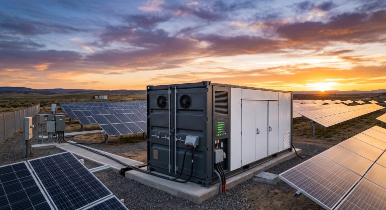
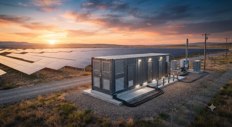
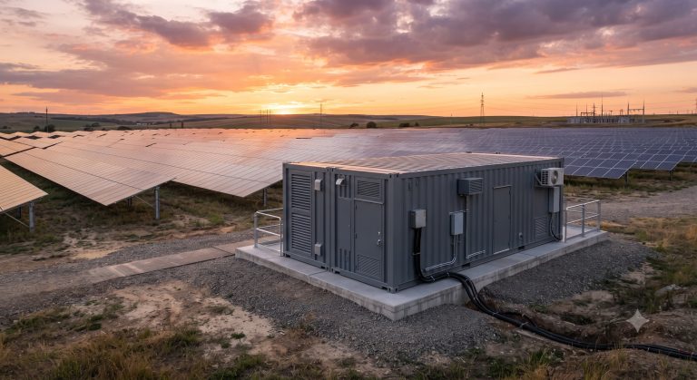
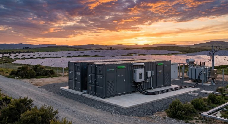
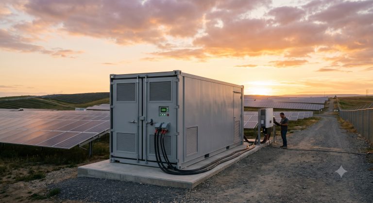
Parallel cluster wiring is typically deployed in containerized or cabinet-based ESS for peak shaving, demand response, and renewable smoothing. Recommended installation practices include: mounting busbars on isolated supports with ≥20 mm clearance; using torque-controlled connections (M10 bolts, 45 N·m); routing communication cables separately from power cables to avoid EMI; and labeling each cluster with unique ID and polarity. Commissioning requires sequential cluster energization: first cluster at open-circuit voltage, then each subsequent cluster matched to within ±0.5 V before paralleling. Regular maintenance includes thermal imaging of busbar joints and verification of BMS balancing logs. This architecture supports both indoor and outdoor pad-mounted deployments, with optional liquid-cooling interfaces for high-ambient environments.
📥 Download Technical Specification
Click the button below to view or download the full official PDF datasheet.