Introduction: The Commercial Energy Storage Imperative
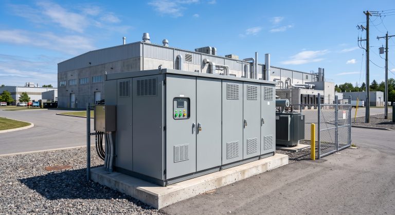
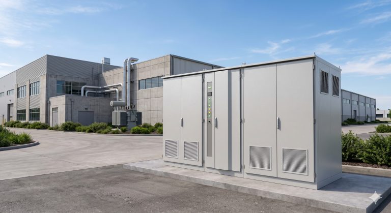
Commercial and industrial (C&I) facilities across the globe are facing an unprecedented convergence of pressures: volatile electricity tariffs, aggressive decarbonization mandates, and the urgent need for grid resilience. At the heart of every modern Battery Energy Storage System (BESS) lies a critical, often underestimated component—the Power Conversion System (PCS). Far more than a simple inverter, the PCS is the intelligent gateway that governs bi-directional energy flow, conditions power quality, and enables seamless interaction between Tier-1 LFP battery racks, renewable generation assets, and the utility grid.
This comprehensive B2B sourcing guide dissects the Power Conversion System (PCS) from an engineering, procurement, and financial perspective. We will explore its core architecture, thermal management strategies including liquid cooling, compliance with IEC 62619 and UL 9540, and the quantifiable ROI levers—peak shaving, demand response, and round-trip efficiency—that determine total cost of ownership (TCO). Whether you are a system integrator, EPC contractor, or facility energy manager, this analysis provides the data-driven framework needed to specify, procure, and deploy a PCS that maximizes asset value over a 10–15 year operational lifespan.
Core Architecture: PCS, BMS, and the Bi-Directional Energy Bridge
Power Conversion System (PCS) Topology
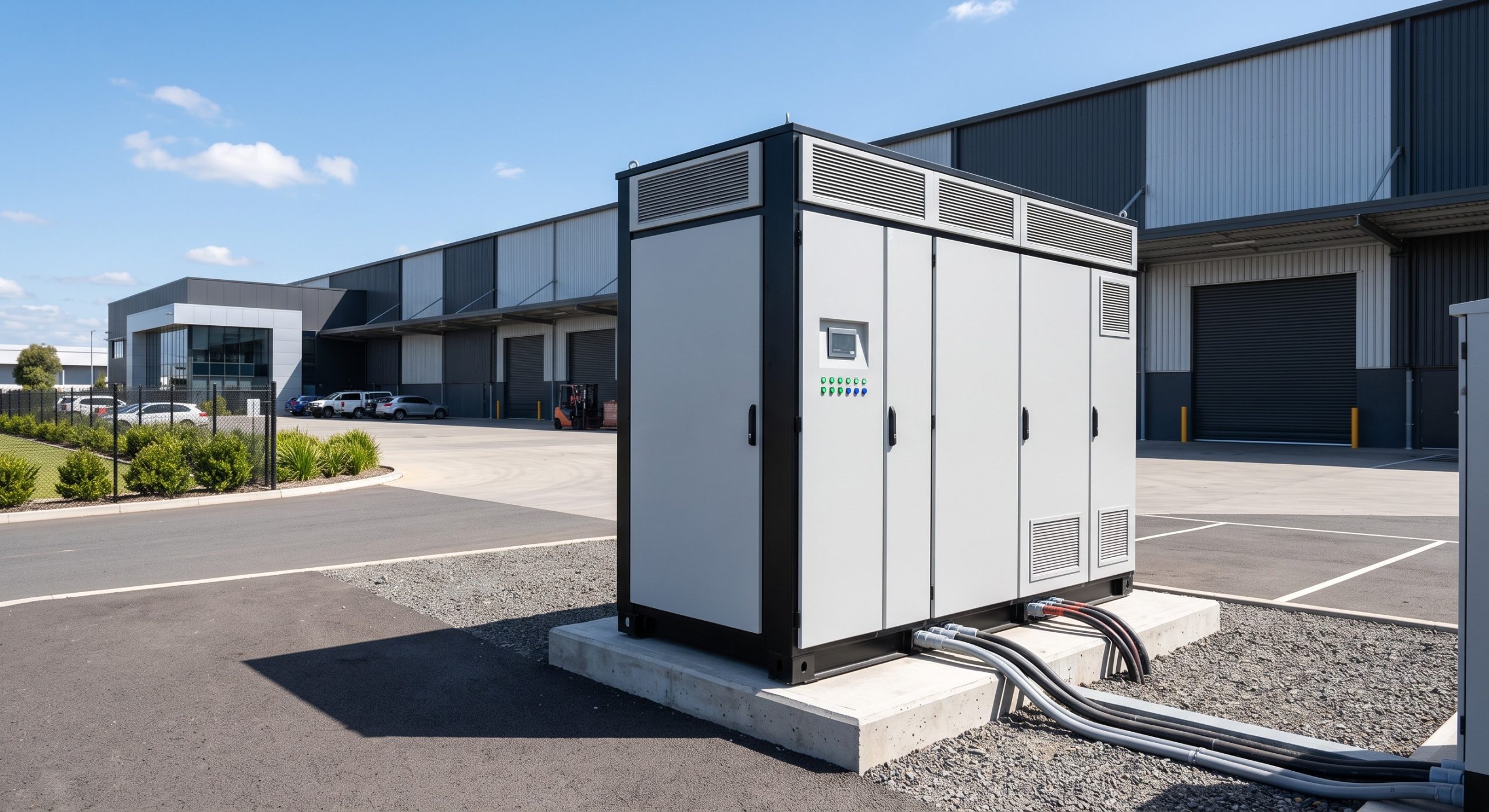
The Power Conversion System (PCS) functions as the controllable interface between the DC bus of the battery energy storage system and the AC grid or local loads. A modern C&I PCS typically employs a three-level IGBT-based topology with advanced Space Vector Pulse Width Modulation (SVPWM) control. This architecture achieves conversion efficiencies exceeding 98.5% in rectifier mode and 98.2% in inverter mode, contributing to an overall system round-trip efficiency (RTE) of 88–92% when accounting for battery, thermal management, and auxiliary losses.
Key functional blocks include:
- AC/DC Rectifier: Converts grid AC to DC for battery charging, with power factor correction (PFC) maintaining THDi < 3%.
- DC/AC Inverter: Discharges stored DC energy to AC loads or grid, supporting four-quadrant operation for reactive power compensation.
- DC/DC Converter (Optional): Enables independent voltage regulation for parallel battery racks, optimizing State of Charge (SoC) balancing.
- LCL Filter: Attenuates high-frequency harmonics to meet IEEE 519 power quality standards.
- Isolation Transformer (Galvanic): Provides electrical isolation and voltage matching for 400V/480V/690V grid interfaces.
Battery Management System (BMS) Integration
The PCS does not operate in isolation. Its performance is tightly coupled with the Battery Management System (BMS), which monitors cell-level voltage, temperature, and State of Health (SoH). For Tier-1 LFP (Lithium Iron Phosphate) cells, the BMS enforces Depth of Discharge (DoD) limits—typically 90% for optimal cycle life—and executes active cell balancing to prevent premature degradation. The PCS responds to BMS commands with millisecond-level precision, adjusting charge/discharge currents to maintain cell voltage windows of 2.5V–3.65V and temperature gradients below 5°C across modules.
Thermal Control: Liquid Cooling vs. Air Cooling in PCS and Battery Racks
Liquid Cooling Thermal Management
High-power C&I PCS units and high-density LFP battery cabinets generate substantial heat during rapid charge/discharge cycles. Liquid cooling has emerged as the superior thermal control strategy for MWh-scale deployments. A typical liquid-cooled PCS employs a 50/50 ethylene glycol-water coolant circulated through cold plates mounted directly on IGBT modules and battery cell surfaces. This approach maintains cell temperatures within a narrow band of ±2°C, significantly reducing thermal runaway risk and extending cycle life by 20–30% compared to air-cooled equivalents.
- Heat Rejection Capacity: Liquid cooling systems can dissipate 5–10 kW per PCS cabinet, enabling continuous full-power operation at ambient temperatures up to 50°C.
- Parasitic Load: Coolant pumps and fans consume 2–4% of system rated power, a critical factor in RTE calculations.
- Maintenance: Closed-loop liquid systems require annual coolant quality checks and filter replacement, with a design life of 10+ years.
Air Cooling Limitations
While air cooling remains viable for smaller 100–250 kW PCS units, its effectiveness diminishes rapidly in high-density configurations. Air-cooled systems typically exhibit cell temperature gradients of 8–12°C, accelerating localized degradation and reducing usable capacity. For MWh-scale projects requiring >8000 cycles, liquid cooling is the de facto standard.
Technical Specifications: Core Parameters for Procurement
The following specification ledger represents a typical 500 kW / 1 MWh C&I BESS with integrated PCS. Procurement teams should use this as a baseline for RFQ development and vendor comparison.
| Key Parameter | Technical Specification |
|---|---|
| Battery Chemistry | Tier-1 LFP (Lithium Iron Phosphate) |
| System Capacity | 1 MWh (expandable to 10 MWh via parallel cabinets) |
| PCS Rated Power | 500 kW (bi-directional, four-quadrant) |
| Cycle Life | >8000 cycles @ 90% DoD, 25°C |
| Round-Trip Efficiency | ≥90% (DC-DC), ≥88% (AC-AC) |
| Depth of Discharge (DoD) | 90% maximum recommended |
| Cooling Method | Liquid cooling (50/50 glycol-water) |
| Operating Temperature | -20°C to +50°C (derated above 45°C) |
| Communication Protocols | Modbus TCP, IEC 61850, CAN 2.0B |
| Certifications | IEC 62619, UL 9540, CE, UN38.3 |
| Protection Rating | IP54 (cabinet), NEMA 3R equivalent |
| Grid Support Functions | Peak shaving, frequency regulation, volt-VAR, demand response |
| Design Life | 15 years (PCS), 10 years (battery racks) |
Commercial ROI: Peak Shaving, Demand Response, and LCOE Optimization
Peak Shaving and Demand Charge Reduction
For C&I facilities subject to time-of-use (TOU) tariffs and demand charges, the PCS enables strategic discharge during peak pricing windows. A 1 MWh system with 90% DoD and 90% RTE delivers approximately 810 kWh of usable energy per cycle. In regions with peak demand charges of $20–$35 per kW, a 500 kW PCS can shave 500 kW from the facility’s peak load, yielding annual savings of $120,000–$210,000—often sufficient to achieve payback in 4–6 years.
Demand Response and Ancillary Services
Advanced PCS units support grid synchronization in <20 ms and can participate in frequency regulation markets. In PJM or ERCOT territories, a 1 MW aggregated BESS can generate $40,000–$80,000 annually from ancillary service revenues. The PCS must comply with IEEE 1547 and UL 1741 SA for grid-tie interoperability, enabling ride-through capabilities and volt-VAR support.
Levelized Cost of Storage (LCOS)
LCOS for a 1 MWh / 500 kW system with >8000 cycles and 90% DoD typically ranges from $0.08–$0.14 per kWh, depending on capital cost, financing, and O&M. The PCS accounts for approximately 15–20% of total CapEx but influences >40% of operational efficiency—making it the highest-leverage component in TCO optimization.
Deployment Scenarios: From Industrial Parks to EV Supercharging
Industrial Park Micro-Grids
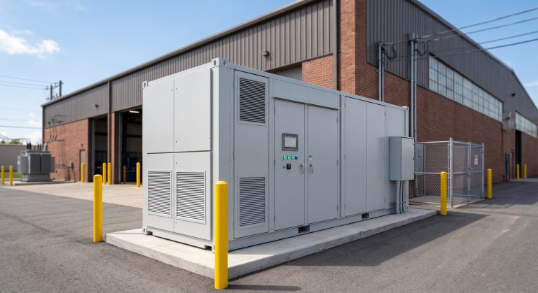
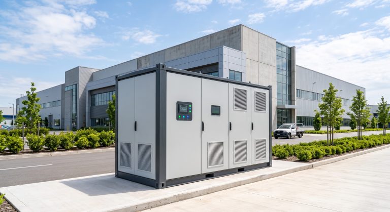
Modular PCS cabinets can be paralleled to form multi-megawatt micro-grids serving industrial parks with 5–50 MW loads. Containerized 20-foot or 40-foot enclosures house PCS, battery racks, and thermal management systems, enabling turnkey outdoor installation with IP54/NEMA 3R protection.
PV-Storage-Charging (光储充) Integration
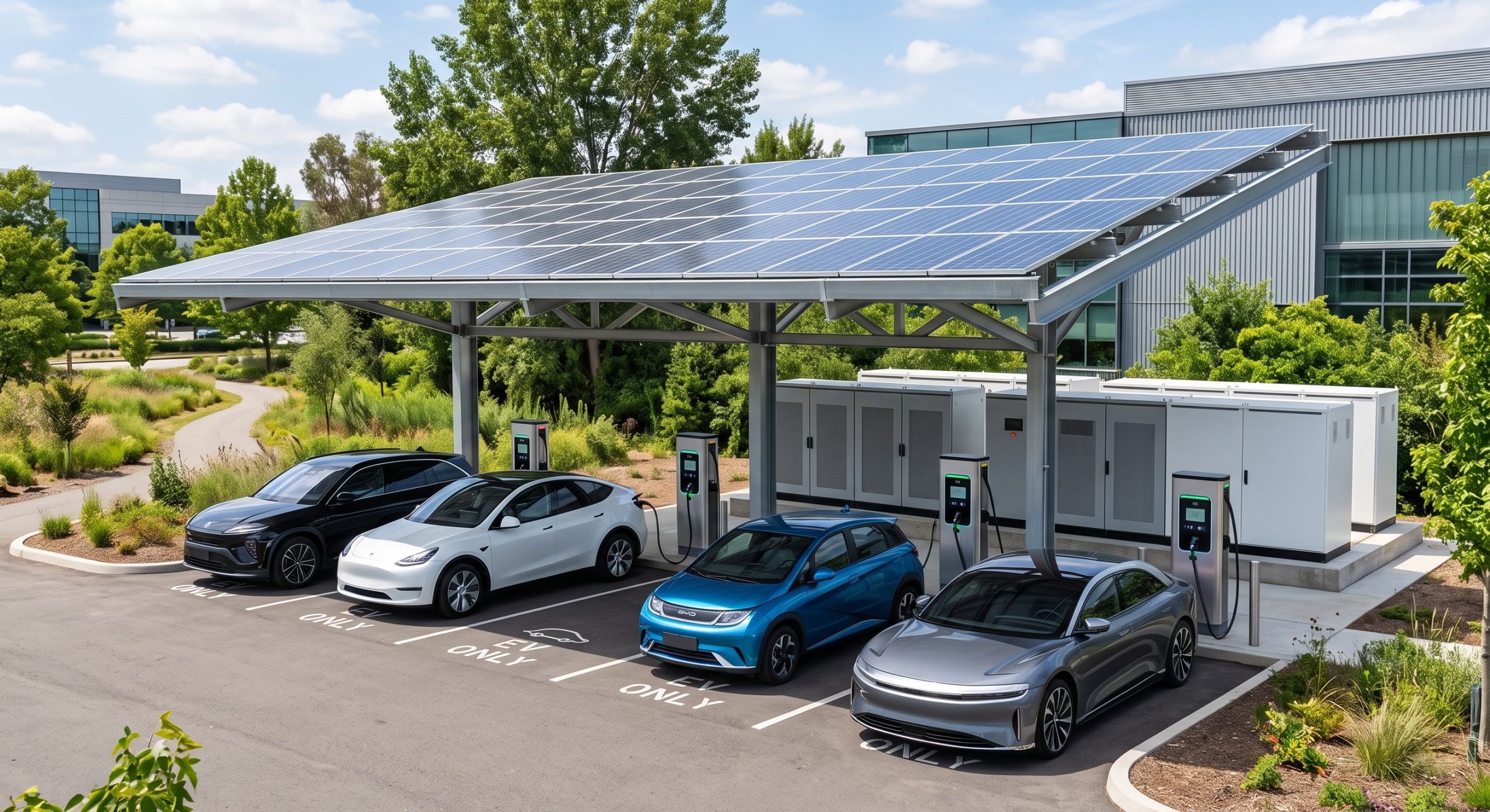
The PCS serves as the pivotal interface in PV-Storage-Charging architectures, coordinating solar canopy DC output, battery charging, and EV supercharger loads. With DC-coupled or AC-coupled configurations, the PCS ensures seamless source switching and peak shaving for high-power 350 kW+ charging stations.
Conclusion: Strategic Procurement for Long-Term Resilience
The Power Conversion System (PCS) is the decisive component that determines whether a C&I energy storage investment delivers 8,000+ cycles of reliable service or becomes an underperforming asset. By prioritizing liquid cooling, IEC 62619 and UL 9540 compliance, >98% conversion efficiency, and advanced BMS integration, procurement teams can secure a PCS that maximizes round-trip efficiency, minimizes LCOS, and future-proofs facilities for demand response, EV charging, and zero-carbon migration. The data is clear: the PCS is not a commodity—it is the strategic enabler of commercial energy independence.