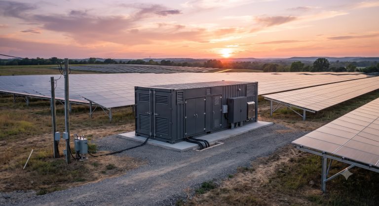
ADVANCED THERMAL RUNAWAY SUPPRESSION ENGINE FACT SHEET: ENERGY STORAGE COOLING SYSTEM MAINTENANCE MANUAL
EXECUTIVE SUMMARY
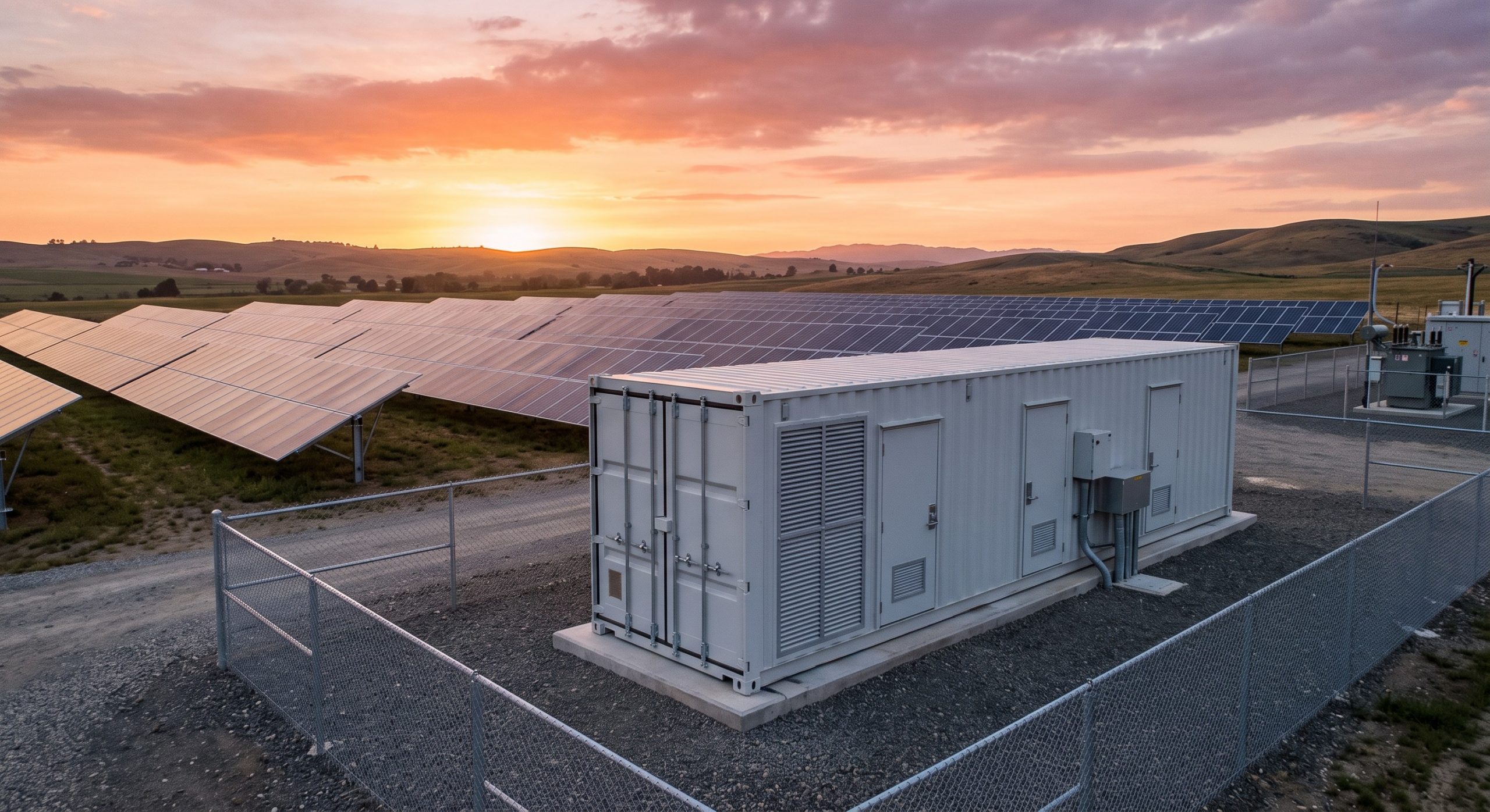
This document serves as the definitive technical reference and maintenance manual for the liquid cooling system integrated within our Tier-1 Energy Storage System (ESS) platform. Designed for commercial and industrial (C&I) applications, this manual provides comprehensive procedures for ensuring optimal thermal management, thereby maximizing system longevity, safety, and operational efficiency. Adherence to the protocols outlined herein is critical for maintaining the system’s performance, achieving the guaranteed cycle life, and upholding all relevant safety certifications.
SYSTEM ARCHITECTURE & SAFETY
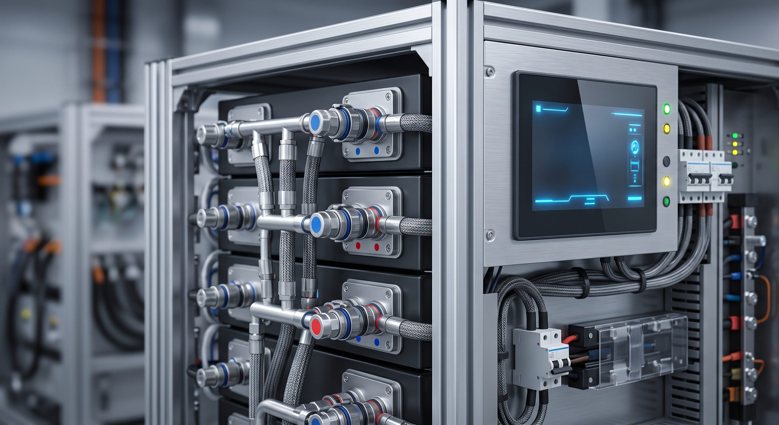
The cooling system is a closed-loop, variable-flow liquid circuit engineered to maintain the LFP battery cells within a narrow optimal temperature band of 20°C to 35°C. The primary components include a chiller unit, a variable-speed pump, a plate heat exchanger, a deionization filter, a coolant reservoir, and a network of stainless-steel and rubber hoses connecting to the battery module cold plates. The system is governed by the Battery Management System (BMS), which modulates coolant flow and chiller output based on real-time cell temperature data, internal resistance, and charge/discharge rates. A key safety feature is the dual-redundant temperature monitoring system, which triggers an automatic safety shutdown and system alarm should temperatures exceed preset thresholds, effectively acting as a primary defense mechanism in the thermal runaway prevention strategy.
KEY FEATURES
– Predictive Thermal Modeling: The proprietary control algorithm integrates predictive thermal modeling, anticipating load changes and pre-adjusting coolant temperature to prevent thermal spikes.
– Redundant Safety Circuits: Dual-redundant circuits monitor coolant pressure, temperature, and flow rate, triggering alarms and protective actions for any deviations.
– Self-Diagnostics: The system performs a self-diagnostic routine every 10 seconds, logging data for predictive maintenance analysis.
– Smart Control Interface: The EMS touch panel provides a real-time, interactive display of the cooling system’s status, including inlet/outlet temperatures, flow rates, and energy consumption.
COMPLIANCE & STANDARDS
This cooling system and its maintenance procedures have been validated to meet the requirements of UL 9540, IEC 62619, and UN 38.3. The coolant used is a non-toxic, biodegradable fluid, and all system components are RoHS and REACH compliant. The maintenance schedule and protocols are structured to ensure that the system remains in full compliance with global safety and operational standards throughout its 15-year design life.
TECHNICAL SPECIFICATIONS
The technical specifications are detailed in the parameter registry below. These parameters are critical for field engineers and O&M personnel to understand when conducting maintenance and troubleshooting.
| Parameter | Specification |
|---|---|
| Cooling Method | Active Smart Liquid Cooling (Variable Flow) |
| Nominal Capacity (per Cabinet) | 215 kWh / 372 kWh (LFP) |
| Coolant Type | Deionized Water with Glycol Mix (Non-toxic) |
| Cooling Capacity (Max) | 15 kW per 100 kWh Module |
| Control Strategy | Predictive PID Control via BMS/EMS |
| Safety Shutdown Threshold | >55°C Cell Temperature |
| Redundancy | N+1 Redundant Pumps & Sensors |
| Ingress Protection (Chassis) | IP54 / IP65 (Outdoor Rated) |
| Operating Temperature Range | -20°C to +50°C Ambient |
| EMC Classification | Class A (Industrial Environments) |
INDUSTRIAL DEPLOYMENT & MAINTENANCE SCHEDULE
Regular maintenance is vital. A monthly visual inspection should include checking for leaks, verifying coolant levels, and inspecting all electrical connections for corrosion. Quarterly, a more detailed inspection should involve testing the deionization filter and analyzing a coolant sample for pH and conductivity. An annual overhaul, to be performed by a certified technician, should include replacing the deionization filter, performing a full system flush, and recalibrating the temperature sensors. All maintenance activities must be logged in the system’s digital O&M log for warranty and compliance traceability.
📥 Download Technical Specification
Click the button below to view or download the full official PDF datasheet.