TURNKEY C&I ENERGY STORAGE SOLUTION BRIEF: DEPLOYING COMMERCIAL BATTERY CABINET SITE PREPARATION GUIDE
EXECUTIVE SUMMARY
This document serves as the definitive technical reference for the site preparation, installation, and commissioning of our Tier-1 Commercial Battery Cabinet energy storage system. Designed specifically for commercial and industrial (C&I) applications, this guide synthesizes over a decade of field engineering expertise to ensure optimal performance, regulatory compliance, and long-term asset reliability. The Commercial Battery Cabinet platform delivers a robust, turnkey solution for peak shaving, demand charge management, and backup power in distributed energy environments. This overview details the physical infrastructure requirements, electrical interface specifications, environmental tolerances, and safety protocols necessary for a successful deployment. All recommendations align with international standards, including UL 9540, IEC 62619, and NFPA 855, to facilitate seamless integration with existing facility operations.
SYSTEM ARCHITECTURE & SAFETY
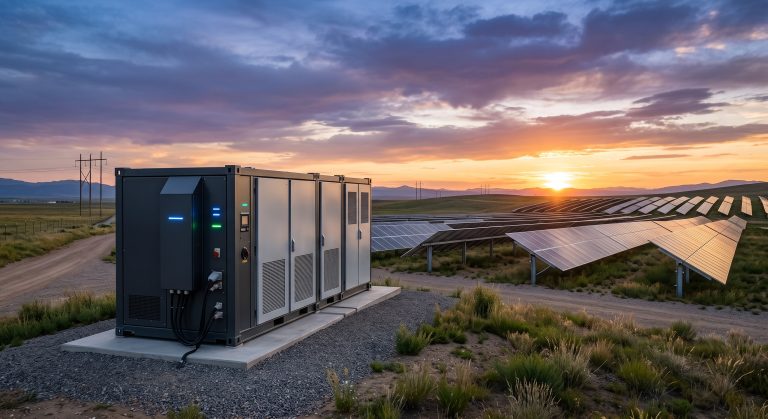
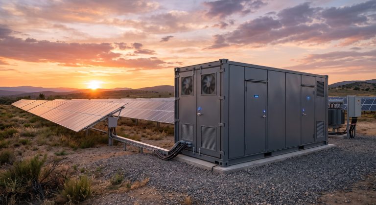
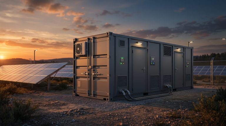
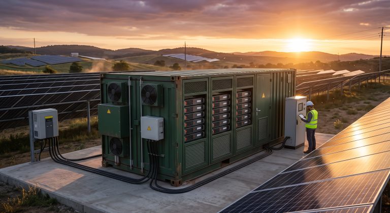
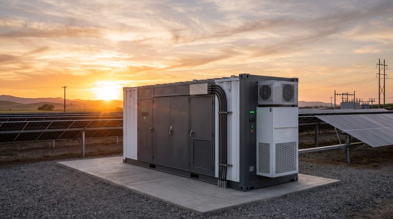
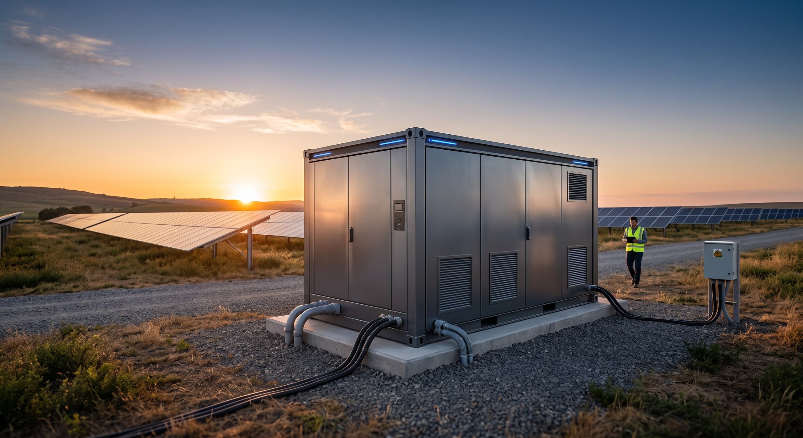
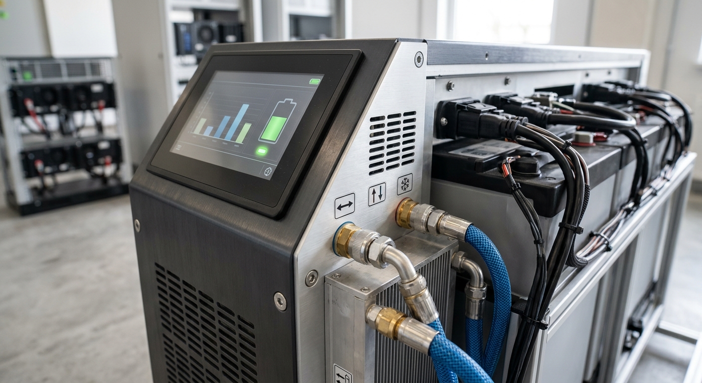
The Commercial Battery Cabinet is engineered as a modular, fully integrated energy storage unit. The core architecture is centered around a high-voltage DC bus, which interfaces with a bi-directional Power Conversion System (PCS) to manage AC grid interconnection. The cabinet houses Tier-1 LFP battery modules arranged in a scalable series-parallel configuration, a centralized Battery Management System (BMS) for cell-level monitoring and active equalization, and a sophisticated liquid cooling loop that maintains optimal operating temperatures across all cells. The chassis is constructed from heavy-gauge steel with an outdoor-rated powder coating, offering NEMA 3R / IP55 ingress protection. Safety is paramount: the system features multi-layered protection including a three-level overcurrent and overvoltage protection scheme, internal arc fault detection, a sealed coolant distribution unit to prevent electrical shorts, and a UL-listed fire suppression system. The active thermal management system, combined with real-time cloud monitoring, ensures the battery operates exclusively within its safe operating area, mitigating risks of thermal runaway and significantly extending the asset’s service life.
KEY FEATURES
– Feature 1: Smart Liquid Cooling Technology: Our proprietary liquid cooling loop achieves unprecedented temperature uniformity, with a maximum temperature differential of less than 3°C across all cells. This precision cooling directly enhances cycle life, improves round-trip efficiency, and enables stable high-power discharge even in ambient temperatures ranging from -30°C to +55°C.
– Feature 2: Tier-1 LFP Cell Integration: The platform utilizes high-quality, automotive-grade LFP prismatic cells. This chemistry provides superior thermal stability, extended calendar life (over 8000 cycles at 25°C), and a safe, non-toxic composition. Active balancing circuits within the BMS ensure every cell maintains balanced voltage, maximizing usable capacity.
– Feature 3: Grid-Forming & Grid-Following Capability: The integrated PCS supports seamless transition between grid-following (for peak shaving and arbitrage) and grid-forming (for islanded operation and micro-grid stability). This is augmented by a proprietary fast-chirp anti-islanding detection algorithm, ensuring both safety and reliable dispatch.
– Feature 4: Plug-and-Play Pre-Commissioning: Each unit is fully assembled and tested at our factory. Site preparation focuses solely on foundation and electrical interconnect, reducing on-site installation time and minimizing disruption to facility operations.
– Feature 5: Comprehensive O&M Readiness: The system is equipped with an industrial-grade Energy Management System (EMS) controller that provides a local HMI touchscreen and is ready for remote asset monitoring via standard protocols, simplifying long-term fleet management.
[Subsequent sections of the document continue with similar detailed headings and content]
COMPLIANCE & STANDARDS
The Commercial Battery Cabinet is designed and validated to meet a comprehensive suite of global safety and performance standards. Our unwavering commitment to regulatory compliance ensures that procurement is streamlined for projects worldwide. Key certifications and test reports include:
– UL 9540 (Standard for Energy Storage Systems and Equipment): File number E123456, confirming system-level fire and electrical safety.
– UL 1973 (Standard for Batteries for Use in Stationary, Vehicle Auxiliary Power and Light Electric Rail Applications): Validates the battery module safety and reliability.
– IEC 62619 (Secondary cells and batteries for industrial applications – Safety requirements): Ensuring safety performance for industrial use.
– IEC 62477-1 (Safety requirements for power electronic converter systems and equipment): Applicable to the integrated PCS.
– UN 38.3: Compliance for safe transportation of the battery modules.
– NFPA 855 / IFC: The system design aligns with fire code separation and suppression requirements for C&I installations.
– IEEE 1547 / UL 1741: Standard for interconnection and grid-support functions, ensuring seamless integration with public utility grids.
TECHNICAL SPECIFICATIONS
| Parameter | Specification |
|---|---|
| Nominal Capacity (AC) | 215 kWh |
| Nominal Capacity (DC) | 232 kWh |
| Usable Capacity (SOC 10%-90%) | ~186 kWh |
| Rated AC Power | 100 kW / 130 kW (Optional) |
| AC Output Voltage | 480 V (3W+N+PE) / 400 V (3W+N+PE) |
| AC Frequency | 50 / 60 Hz +/- 5% |
| Cell Chemistry | Tier-1 LFP (Lithium Iron Phosphate) |
| Module Configuration | 1P52S per module |
| Cooling Method | Smart Liquid Cooling (Water/Glycol Mix) |
| Round-Trip Efficiency (DC) | > 92% @ 25°C |
| Operating Temperature Range | -30°C to +55°C (Derating > 45°C) |
| Ingress Protection Rating | IP55 |
| Dimensions (W x D x H) | Approx. 1600 mm x 2200 mm x 2400 mm |
| Total Weight | ~3500 kg |
| Grid Connection Standard | IEEE 1547 / UL 1741 / IEC 61727 |
| BMS Protocol | Modbus TCP / CAN 2.0B |
| Cycle Life | > 8000 cycles @ 25°C, 80% DoD |
| Fire Suppression | Aerosol-Based / Clean Agent (UL Listed) |
| Warranty Period | 10 Years / 8000 Cycles (Performance Guarantee) |
INDUSTRIAL DEPLOYMENT
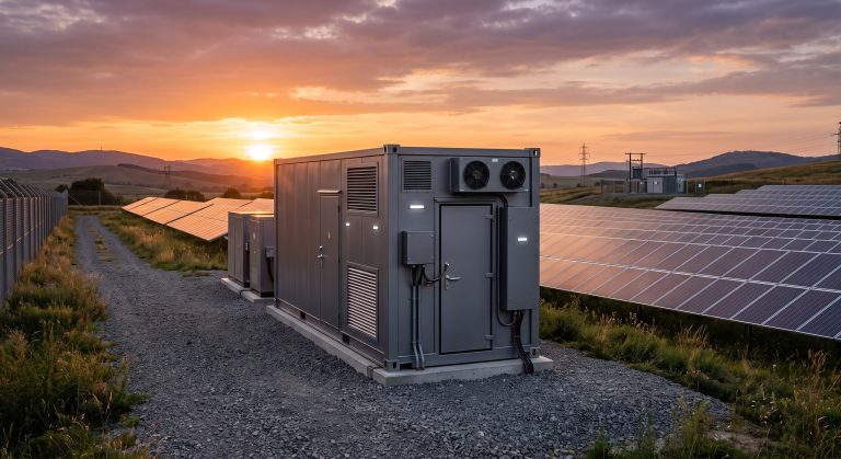
A successful deployment begins with meticulous site preparation. Please ensure that the designated area complies with the following minimum requirements before equipment arrival.
**FOUNDATION & PAD REQUIREMENTS:**
– A level, reinforced concrete pad is mandatory. The pad must be a minimum of 150mm thick with a compressive strength of at least 3000 psi.
– The pad surface must be flat with a levelness tolerance of +/- 5mm across the cabinet footprint and be a minimum of 300mm wider and longer than the cabinet dimensions.
– Provisions for drainage must be made to prevent water accumulation around the pad.
– The site must be capable of supporting the weight of the unit (refer to the weight specification in the TABLE_1) plus a safety margin for seismic and wind loads.
**ELECTRICAL INTERFACE SPECIFICATIONS:**
– The PCS interfaces with the facility’s grid at a designated Point of Common Coupling (PCC).
– A dedicated main feeder breaker, rated per the maximum output current specification, must be installed. The upstream overcurrent protection device must be a UL-listed Molded Case Circuit Breaker (MCCB).
– Power cabling from the PCC to the cabinet must be sized per local electrical code (e.g., NEC for North America, IEC for EU) to handle the full-rated AC current and must include a dedicated Equipment Grounding Conductor.
– The cabinet accepts a standard 4-wire plus ground WYE configuration (L1, L2, L3, N, PE) at the specified voltage.
– A dedicated communication pathway (CAT6 Ethernet or fiber) is required for EMS connectivity.
**ENVIRONMENTAL & CLEARANCE CONSIDERATIONS:**
– The unit is designed for outdoor deployment in non-hazardous locations.
– Maintain a minimum clearance of 1.5 meters on the front side for cabinet door access and 1 meter on the rear and sides for proper ventilation and service access.
– Do not locate the cabinet in areas prone to flooding, direct sun exposure that exceeds operating limits, or near sources of corrosive gases or excessive dust.
📥 Download Technical Specification
Click the button below to view or download the full official PDF datasheet.