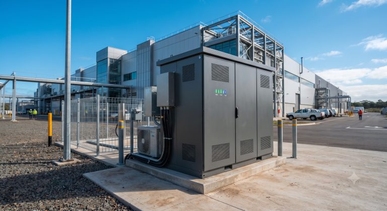
Introduction: The Thermal Bottleneck in Commercial & Industrial Energy Storage
As Commercial & Industrial (C&I) facilities face escalating demand charges and grid instability, the deployment of Smart Energy Management Systems (EMS) for battery energy storage has shifted from a niche sustainability initiative to a core financial strategy. However, the Achilles’ heel of any high-capacity BESS (Battery Energy Storage System) remains thermal management. At the multi-megawatt scale, the difference between liquid cooling and traditional air cooling is not merely a maintenance preference—it is the primary determinant of Round-trip Efficiency (RTE), Cycle Life, and ultimately, Levelized Cost of Storage (LCOS). This deep dive evaluates the engineering supremacy of liquid-cooled architectures within modern Smart EMS for C&I storage, providing a data-driven roadmap for system architects and procurement officers targeting MWh-scale deployments.
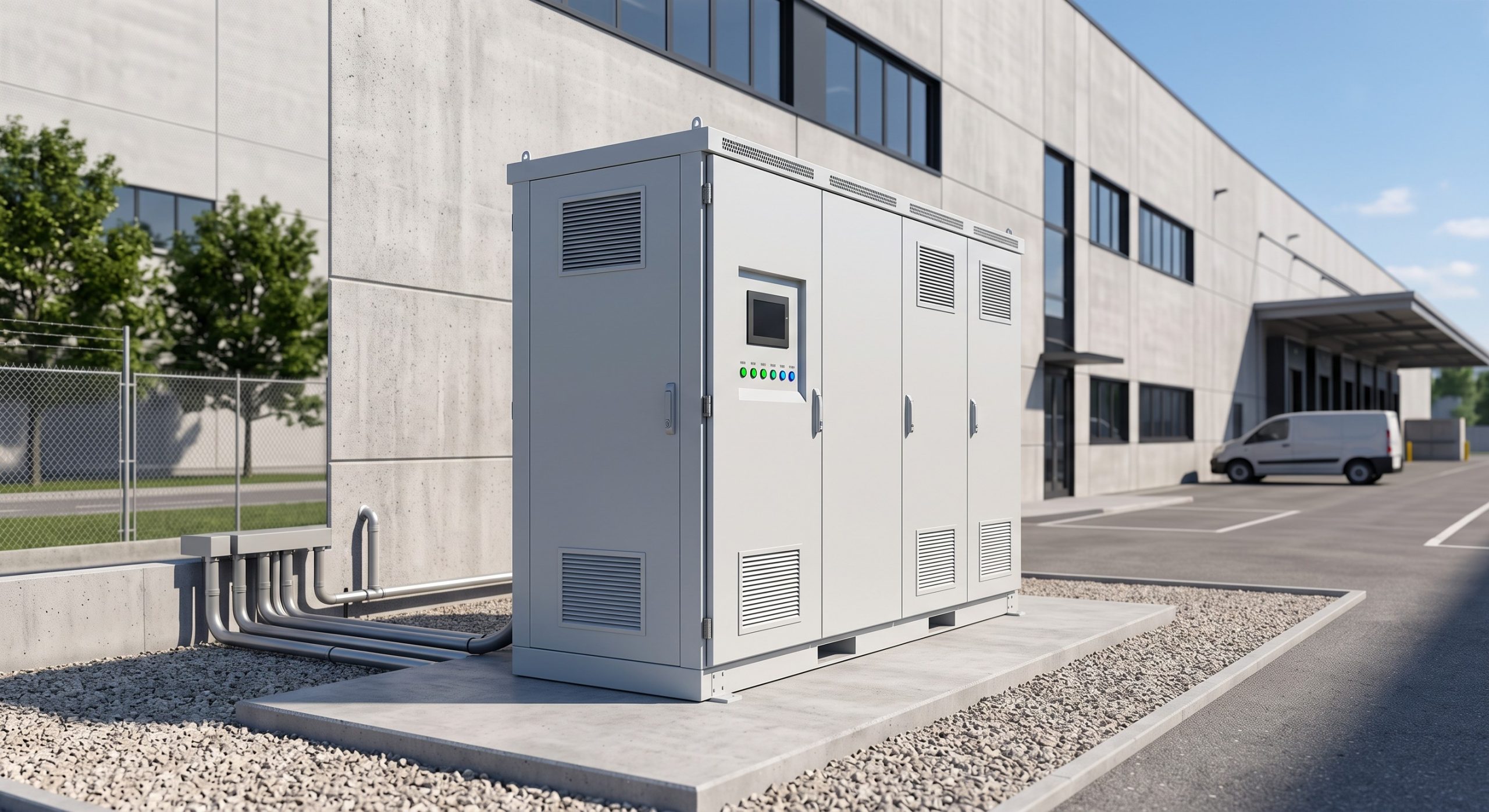
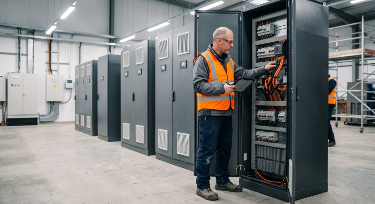
Core Architecture: Smart EMS, PCS, and the Thermal Regulation Imperative
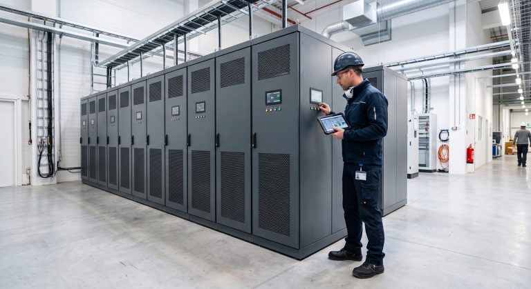
A typical C&I installation comprises Tier-1 LFP (Lithium Iron Phosphate) cells, a Bi-directional PCS (Power Conversion System), and the Smart EMS brain. While the EMS optimizes dispatch logic—executing peak shaving, demand response, and PV-storage-charging synergy—it is the thermal subsystem that dictates whether those commands can be executed at peak amperage without triggering Derating.
Liquid Cooling vs. Air Cooling: The Engineering Delta
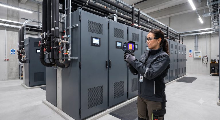
Air cooling relies on forced convection, which is inherently limited by the low thermal conductivity of air (~0.026 W/m·K). In contrast, liquid cooling utilizes glycol-water mixtures with thermal conductivity roughly 25 times higher. This allows for:
- Cell Temperature Uniformity: Maintaining a delta-T of <3°C across the module (vs. >8°C for air cooling), preventing localized degradation.
- Higher C-Rates: Enables continuous 1C charging/discharging without thermal runaway risk, crucial for frequency regulation.
- Footprint Reduction: Eliminating bulky air ducts increases Energy Density by up to 40%, a critical factor for space-constrained industrial parks.
Technical Specifications & Precision Metrics
The following table outlines the benchmark parameters required for a Tier-1 C&I liquid-cooled cabinet designed for UL 9540 and IEC 62619 compliance. These metrics directly influence the Total Cost of Ownership (TCO).
| Key Parameter | Technical Specification (Liquid-Cooled C&I Cabinet) |
|---|---|
| Battery Chemistry | Tier-1 LFP (Lithium Iron Phosphate) |
| System Capacity | 215 kWh to 5 MWh (Modular Parallel Expansion) |
| Cycle Life | >8,000 cycles @ 90% DoD (25°C, 0.5C) |
| Round-trip Efficiency (RTE) | ≥95% (Liquid Cooling) vs. 88-91% (Air Cooling) |
| Depth of Discharge (DoD) | 95% (Usable) |
| Thermal Management | Active Liquid Cooling (Glycol-Water), Delta-T <3°C |
| Cooling Power Consumption | <2% of Rated Capacity (Auxiliary Load) |
| Communication Protocol | Modbus TCP/IP, CAN 2.0, IEC 61850 |
| Certification & Compliance | UL 9540, IEC 62619, UN38.3, CE, NFPA 855 |
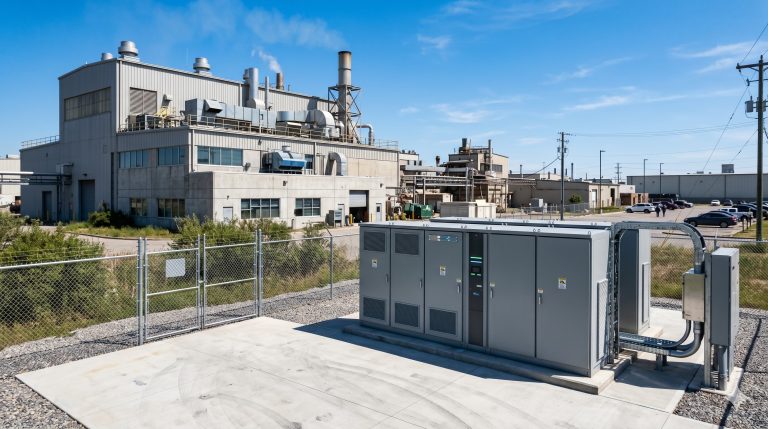
| Ingress Protection | IP54 (Outdoor) / IP20 (Indoor Cabinet) |
| Fire Suppression | Aerosol + Perfluorohexanone (Novec 1230) Multi-level |
Note the Round-trip Efficiency (RTE) of ≥95% for liquid-cooled systems. This 3-4% gain over air-cooled counterparts translates to massive arbitrage gains over an 8000-cycle lifespan. Additionally, UN38.3 transport certification and CE marking are non-negotiable for global deployment.
Commercial ROI, Grid Support, and LCOE Optimization
The financial case for Smart EMS for C&I storage is built on three pillars: Peak Shaving, Demand Charge Management, and Virtual Power Plant (VPP) Participation.
Maximizing Peak-Shaving ROI
By integrating Smart EMS algorithms with liquid-cooled hardware, facility managers can execute millisecond-level load following. The EMS predicts load spikes and discharges the battery to cap the facility’s Maximum Demand (kW). Because liquid cooling allows for a sustained 0.5C to 1C discharge rate without derating, the system can capture the full demand charge reduction, often resulting in CapEx payback periods of 3-5 years.
VPP Readiness and Frequency Regulation
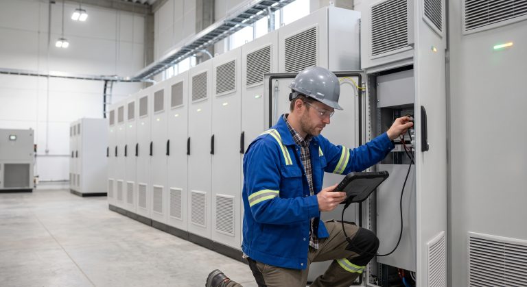
With RTE >95% and DoD >90%, these assets are prime candidates for Frequency Regulation (AGC) markets. The Liquid Cooling system ensures that the rapid, high-frequency charge/discharge cycles required by grid operators do not induce thermal runaway. The BMS (Battery Management System) performs active cell balancing, ensuring that the weakest cell does not limit the entire string’s capacity.
Deployment Scenarios: From EV Supercharging to Industrial Micro-Grids
The versatility of modular Smart EMS for C&I storage extends across multiple high-impact verticals:
- EV Supercharging Hubs (PV-Storage-Charging): Buffering the grid to deliver 350kW+ fast charging without upstream transformer upgrades.
- Industrial Parks: Achieving Energy Independence by integrating with rooftop solar and diesel gen-set replacement.
- Data Centers: Providing UPS-grade backup with zero transfer time and thermal stability.

Conclusion: The Strategic Verdict on Thermal Management
Specifying a Smart EMS for C&I storage without prioritizing Liquid Cooling is a strategic oversight. The marginal CapEx increase for liquid cooling is offset within the first 18 months of operation through reduced auxiliary power consumption (HVAC loads), higher RTE, and the ability to participate in high-value grid services. As IEC 62619 and UL 9540 standards evolve to demand stricter thermal propagation prevention, liquid-cooled architectures will become the default standard for any serious MWh-scale commercial procurement. System architects must mandate delta-T <3°C and IP54+ enclosure ratings to ensure a 15-year asset life.