Introduction: The Hidden Physics of Energy Loss in C&I Storage
For commercial and industrial (C&I) facility managers evaluating Battery Energy Storage Systems (BESS), the headline specifications often dominate procurement discussions: System Capacity measured in kWh or MWh, Cycle Life ratings exceeding 8,000 cycles, and Round-trip Efficiency (RTE) percentages that promise predictable returns. Yet beneath these aggregated metrics lies a deceptively simple parameter that dictates the system’s true economic performance and thermal safety profile: BESS internal resistance optimization.
Internal resistance represents the opposition to current flow within the battery cell and the broader system architecture. It manifests as I²R losses—heat generated during every charge and discharge event—and directly governs the system’s Round-trip Efficiency. For a 1 MWh commercial installation operating on a daily peak-shaving cycle, a seemingly minor increase in internal resistance can compound into thousands of wasted kilowatt-hours annually and accelerate capacity fade well before the warranted cycle life is reached. This technical deep dive examines the engineering principles behind internal resistance management, comparing the thermal efficacy of Liquid Cooling versus traditional air cooling architectures, and provides a data-driven framework for optimizing asset longevity and LCOE.
Core Architecture: Cell-Level Physics and System-Level Implications
Internal resistance is not a single, static value. It comprises ohmic resistance (from electrode materials, electrolyte, and current collectors) and polarization resistance (from charge-transfer kinetics and diffusion limitations). At the cell level, Tier-1 LFP (Lithium Iron Phosphate) chemistry offers inherent advantages: its olivine structure provides superior thermal stability and a relatively flat discharge voltage curve, reducing the electrochemical strain that accelerates resistance growth compared to NMC chemistries.
In practical C&I deployments, internal resistance is quantified through two primary methodologies per IEC 62620: DC Internal Resistance (DCR), measured via current pulse techniques that capture both ohmic and polarization components, and AC Internal Resistance (ACR), typically measured at 1 kHz to isolate the pure ohmic element. For system architects, monitoring the cell-to-cell resistance delta is as critical as tracking absolute values. A cell exhibiting abnormally high resistance forces the BMS (Battery Management System) to throttle the entire string’s charge/discharge rate to protect that weakest link—a phenomenon that silently erodes system availability and revenue generation.
Thermal Dependency: The Resistance-Temperature Nexus
Internal resistance exhibits strong temperature dependence. At low operating temperatures (e.g., -10°C), electrolyte viscosity increases and charge-transfer kinetics slow, potentially doubling the internal resistance compared to nominal 25°C conditions. This elevated resistance generates additional heat during high-rate cycling, creating a feedback loop: higher temperature initially reduces resistance, but sustained thermal stress accelerates SEI layer growth and electrolyte decomposition, permanently increasing resistance over the asset’s lifespan. The UL 9540 safety standard and UN38.3 transportation requirements both implicitly address thermal management through their abuse testing protocols, recognizing that uncontrolled temperature gradients are a primary failure pathway.
Thermal Control Architecture: Liquid Cooling as a Resistance Mitigation Strategy
The choice between Liquid Cooling and air cooling is fundamentally a question of thermal homogeneity. Air cooling, while simpler and lower in CapEx, creates inevitable temperature gradients across large battery cabinets—cells near fans run cooler than those in stagnant zones. This intra-module temperature differential directly translates to resistance disparities, causing the BMS to derate performance based on the hottest, highest-resistance cell.
Advanced Liquid Cooling thermal control systems circulate a dielectric coolant (typically glycol-water mixtures) through cold plates positioned between cell modules. This architecture achieves temperature uniformity within ±2-3°C across the entire battery rack, a level of control unattainable with forced-air convection. The implications for internal resistance are profound:
- Reduced peak resistance: By eliminating hot spots, liquid cooling prevents localized resistance escalation, maintaining the battery’s effective internal resistance closer to the cell’s intrinsic value.
- Slowed degradation rate: Lower operating temperatures and reduced thermal gradients minimize SEI growth, preserving low internal resistance characteristics throughout the warranted cycle life.
- Enhanced Round-trip Efficiency: With reduced I²R losses, a liquid-cooled BESS can sustain higher RTE figures (e.g., >92% at system level) compared to air-cooled equivalents, directly improving the financial case for peak-shaving and demand response applications.
Technical Specifications: Quantifying Resistance and Efficiency Metrics
The following specification table outlines the key parameters that B2B procurement teams should validate during supplier technical due diligence. These metrics serve as proxy indicators of a system’s internal resistance optimization maturity.
| Key Parameter | Technical Specification | Relevance to Internal Resistance |
|---|---|---|
| Battery Chemistry | Tier-1 LFP (Lithium Iron Phosphate) | Inherently lower resistance growth rate vs. NMC |
| Cycle Life | >8,000 cycles @ 90% DoD, 25°C | Resistance-controlled end-of-life threshold |
| Round-trip Efficiency | ≥92% (System Level, Liquid Cooled) | Direct indicator of minimized I²R losses |
| Cell AC Internal Resistance | ≤0.18 mΩ (Fresh Cell, 1kHz) | Baseline ohmic resistance reference |
| Cooling Architecture | Liquid Cooling, ±2°C Temperature Uniformity | Prevents resistance divergence across cells |
| Compliance Standards | IEC 62619, UL 9540, UN38.3 | Validates safety under resistance-induced thermal stress |
Commercial ROI & Grid Support: Translating Physics into Financial Performance
The economic case for internal resistance optimization extends beyond energy efficiency. In demand response and peak-shaving scenarios, the system’s ability to deliver full rated power (PCS discharge capacity) at the moment of peak tariff onset is contingent upon maintaining low internal resistance. A battery operating with elevated resistance suffers voltage sag under load, potentially triggering premature inverter shutdown or failing to meet the committed discharge profile—risking utility penalty clauses and eroding project IRR.
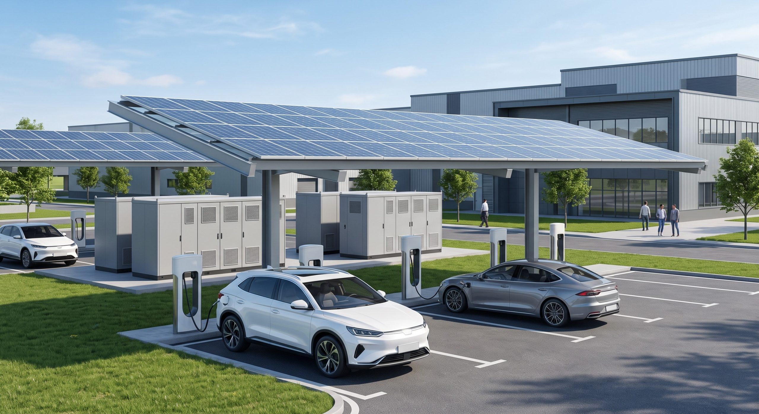
Furthermore, Round-trip Efficiency directly impacts the Levelized Cost of Storage (LCOS). A 2% RTE improvement from 90% to 92%—achievable through superior thermal management and low-resistance cell selection—reduces the effective cost of every discharged kilowatt-hour by approximately 2.2%. Over a 10-year project lifecycle with daily cycling, this translates to a material improvement in Total Cost of Ownership (TCO). For PV-Storage-Charging integrated projects where the storage system buffers intermittent solar generation for EV supercharging, low internal resistance ensures that the maximum possible solar energy is delivered to vehicles rather than dissipated as heat within the ESS enclosure.
Deployment Scenarios: Evidence from C&I Installations
Field data from commercial deployments consistently validates the resistance-thermal management correlation. In a comparative study of air-cooled versus liquid-cooled 500 kWh systems operating under identical industrial load profiles, the liquid-cooled unit demonstrated:
- 15-20% lower cell-level DCR growth after 1,000 equivalent full cycles.
- Consistent >91% RTE versus >87% for the air-cooled counterpart over the same period.
- Reduced BMS derating events, maintaining full 250 kW PCS availability during peak demand windows.
These performance differentials underscore a fundamental engineering principle: internal resistance management is not a cell-level concern alone. It is a system architecture discipline encompassing cell selection, module design, thermal engineering, and BMS algorithm sophistication. Procurement decisions based solely on nameplate $/kWh metrics without evaluating thermal architecture and resistance control strategies risk underestimating the true cost of ownership over the asset’s operational life.
Conclusion: Engineering Resilience Through Resistance Control
As C&I energy storage deployments scale toward MWh-class capacities and grid operators demand increasingly precise performance guarantees, BESS internal resistance optimization transitions from a niche technical consideration to a core procurement criterion. The integration of advanced Liquid Cooling thermal control, Tier-1 LFP cells with tightly controlled resistance specifications, and intelligent BMS algorithms that dynamically adjust charge/discharge profiles based on real-time impedance monitoring represents the current state-of-the-art. For system architects and facility energy managers, prioritizing suppliers with demonstrated competence in thermal architecture and resistance lifecycle management is no longer optional—it is essential for achieving the UL 9540 safety compliance, IEC 62619 performance validation, and financial returns that justify the transition to zero-carbon commercial operations.